
Unbalanced Magnetron Sputtering: A Simulation Case Study
Magnetron sputtering is one of the most widely used physical vapour deposition (PVD) techniques for thin films and coatings. Magnets behind the target confine electrons close to it, which boosts ionisation of the process gas and sustains the discharge. The magnetic configuration also decides how much plasma reaches the substrate.
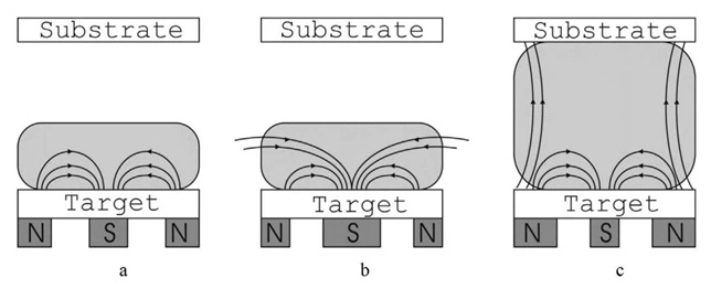
In a balanced magnetron, most field lines close between the central and outer poles near the target. In an unbalanced magnetron the two poles have different strengths, so some field lines reach farther towards the substrate, which can raise the ion flux there. The effect depends on the actual field and operating conditions, not on the label “unbalanced” alone.
This article covers why unbalanced magnetrons are used, why Type II configurations matter for magnetic-induced ion bombardment, and how unbalance can be quantified. For the basics, see our companion article, “Balanced and Unbalanced Magnetron Sputtering.”
Why Use An Unbalanced Magnetron?
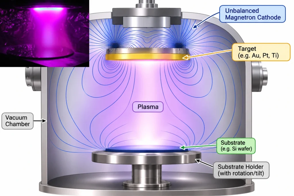
In a conventional magnetron most of the plasma stays close to the target, so the ion current reaching the substrate can be too low for processes that benefit from ion bombardment. A Type II unbalanced magnetron lets electrons, and therefore ionisation, extend into the space between target and substrate (Figure 1), which raises the ion current at the growing film. With substrate bias, the magnetic configuration sets how many ions are available, while the sheath voltage and substrate bias set how hard they collide the substrate.
Typical Use Cases
- Hard and wear-resistant coatings: magnetic-induced ion bombardment can densify nitride films such as TiN and CrN and improve adhesion.
- Dense films at low temperature: ion assistance can compact a film without simply raising the substrate temperature.
- Diamond-like carbon (DLC): controlled bombardment during growth helps tune film density and stress.
- Optical and protective thin films: denser, more compact layers can improve durability and barrier performance.
- Batch coating of complex parts: in closed-field systems, neighbouring unbalanced magnetrons of opposite polarity link their fields and keep the plasma around the substrates.
It should be notes that too much ion bombardment can heat the substrate, increase film stress, re-sputter the film or damage sensitive layers, so the goal is not to reach the maximum unbalance, but to sustain a useful ion flux and energy for the required coating.
Type I and Type II Unbalanced Magnetrons
The classic classification depends on which pole is stronger:
- Type I: the central pole is stronger. Its open field lines tend to run to the chamber walls, so it is less effective at delivering ion current to the substrate.
- Type II: the outer pole is stronger. More open field extends from the cathode edge towards the substrate, helping electron transport and potentially raising the ion current there.
These types describe field topology, where a Type II cathode can be tuned towards balance. Ions also do not simply follow field lines: electrons are more dynamic than ions because of their inferior mass. The field changes where electrons go and where ionisation happens, and the resulting plasma and sheath conditions set the ion flux and energy at the substrate. The Type II label alone therefore does not fix the ion flux.
How Can Magnetic Unbalance Be Quantified?
Unbalance can be described by the flux ratio of the poles, by geometric parameters taken from the field, or by measurements such as substrate ion current. These are related but not identical. One useful geometric descriptor is the coefficient of geometrical unbalance, KG, introduced by Svadkovski, Golosov and Zavatskiy. First, two features that are often confused need separating.
The Axial Magnetic Null Point
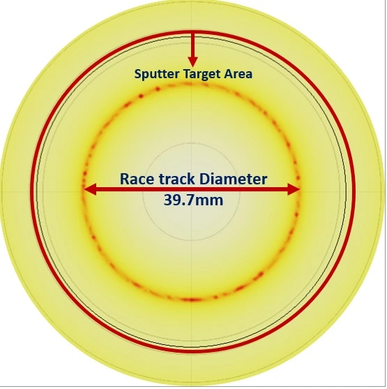
On the axis of a planar, approximately axisymmetric cathode, the axial null point is where the axial field component Bz crosses zero. By symmetry the whole field vector vanishes there in an ideal axisymmetric model (in a 3D model, Bz = 0 alone does not guarantee |B| = 0). Its height znull is measured from the plasma-facing target surface (z = 0). It is not the same as the circular Bz = 0 ring on the target surface that marks the racetrack and the zone of concentrated erosion, although both come from the same magnetic configuration.
The Coefficient of Geometrical Unbalance, KG
The coefficient compares the null-point height with the racetrack diameter:
KG = znull / (2 rrt)
- znull : The axial distance from the target surface to the axial magnetic null point.
- rrt : The average radius of the erosion racetrack, so 2 rrt is its average diameter.
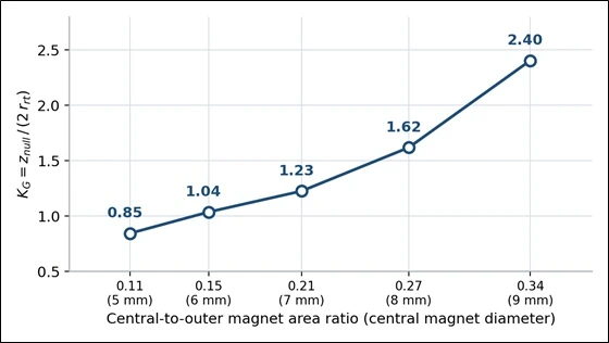
KG is dimensionless, so it is a convenient way to track a cathode design as the magnets change. Increasing the central magnet moves the null farther above the target, which in the series below we read, together with the field plots, as movement towards the balanced regime. This is not a universal rule that a larger KG always means a more balanced magnetron. The parameters in a cathode construction, including target-to-magnet distance, target thickness, yoke and pole dimensions differ from one design to another; so a KG value, and any range marking the move from unbalanced to balanced behaviour, belongs to a specific design. Golosov, for example, found balanced fields at KG of about 1.235–1.27 in the systems he studied, which should not be assumed for a different cathode. Within one design, KG remains a meaningful way to see how the field changes.
Case Study: Magnetic Field Simulations
Simulated Cathode Paramters
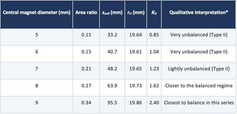
For better explanation, a simulation of a yoke-backed cathode is presented. Here, the outer magnetic ring was fixed (30 mm outer radius, 1 mm radial width, 10 mm height) and N42 magnets were used throughout. Only the central magnet diameter was varied, from 5 to 9 mm. The area ratio is expressed as central magnet area divided by outer ring area. With the same height and grade, this is a rough proxy for the relative strength of the two poles.
Simulation Results
The results of the simulation are listed in Table 1. The null height and racetrack radius were extracted from each simulation and KG calculated with the definition above. The labels in the last column describe the progression within this model only; they are not KG thresholds.
Comparing The Simulated Field Configurations
As the area ratio rises, the null point goes higher, while the racetrack radius varies just about 1.3% around its mean. The shifts in the axial null is depicted in Figure 5, considering the measures strongly depend on the initial parameters, and a different cathode design would give different null heights.
Figure 5 shows the five cross-sections in order of increasing area ratio, with the null height marked on each. They are for qualitative comparison of field topology.
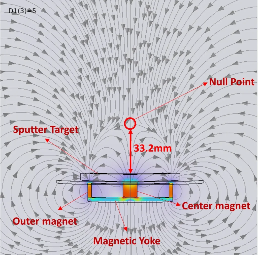
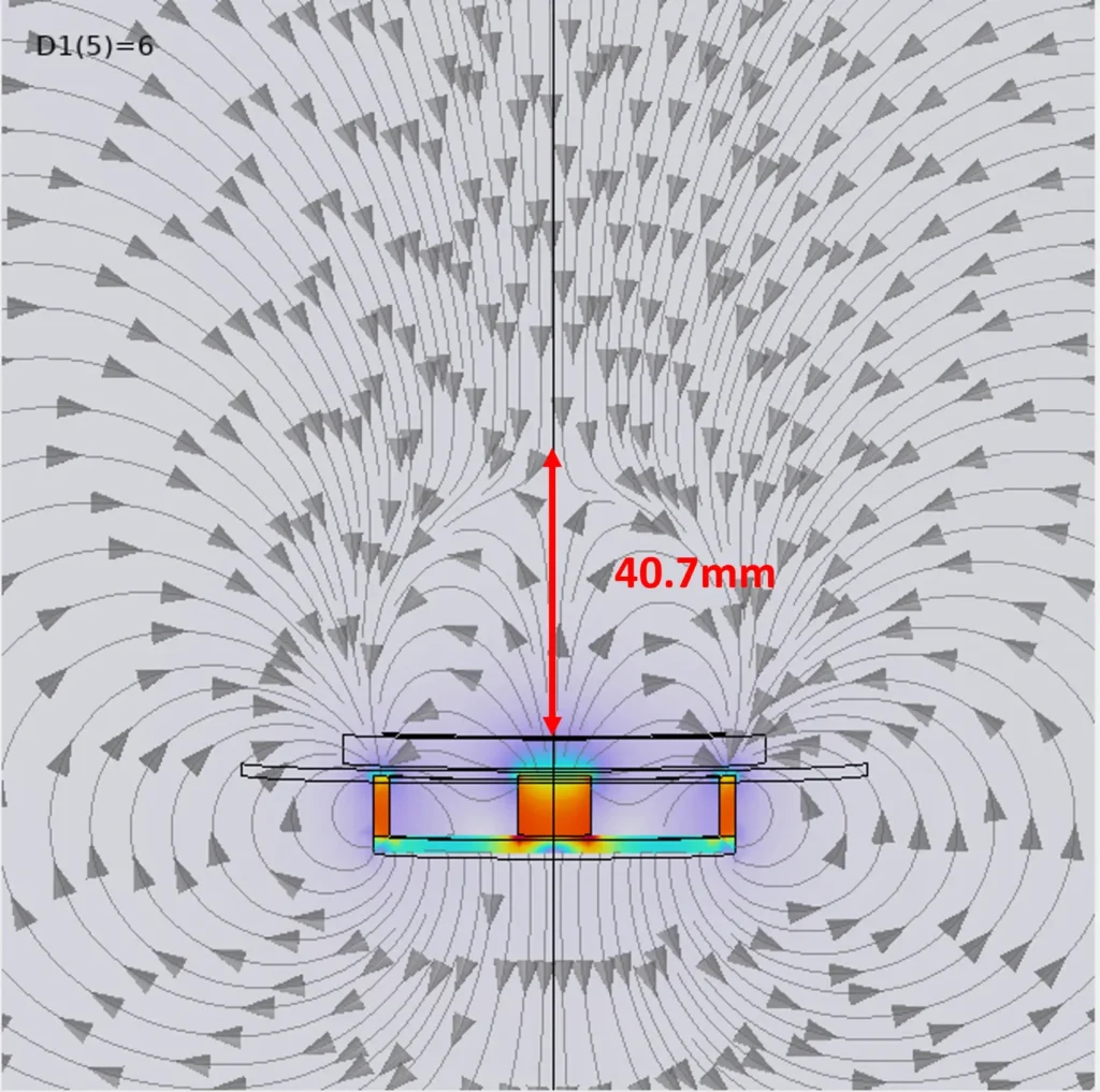
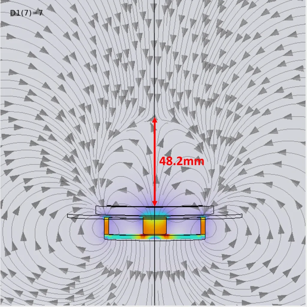
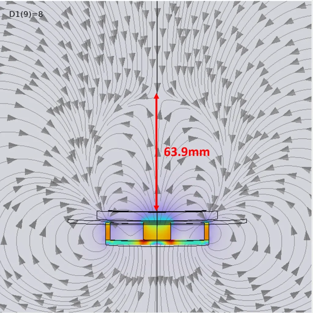
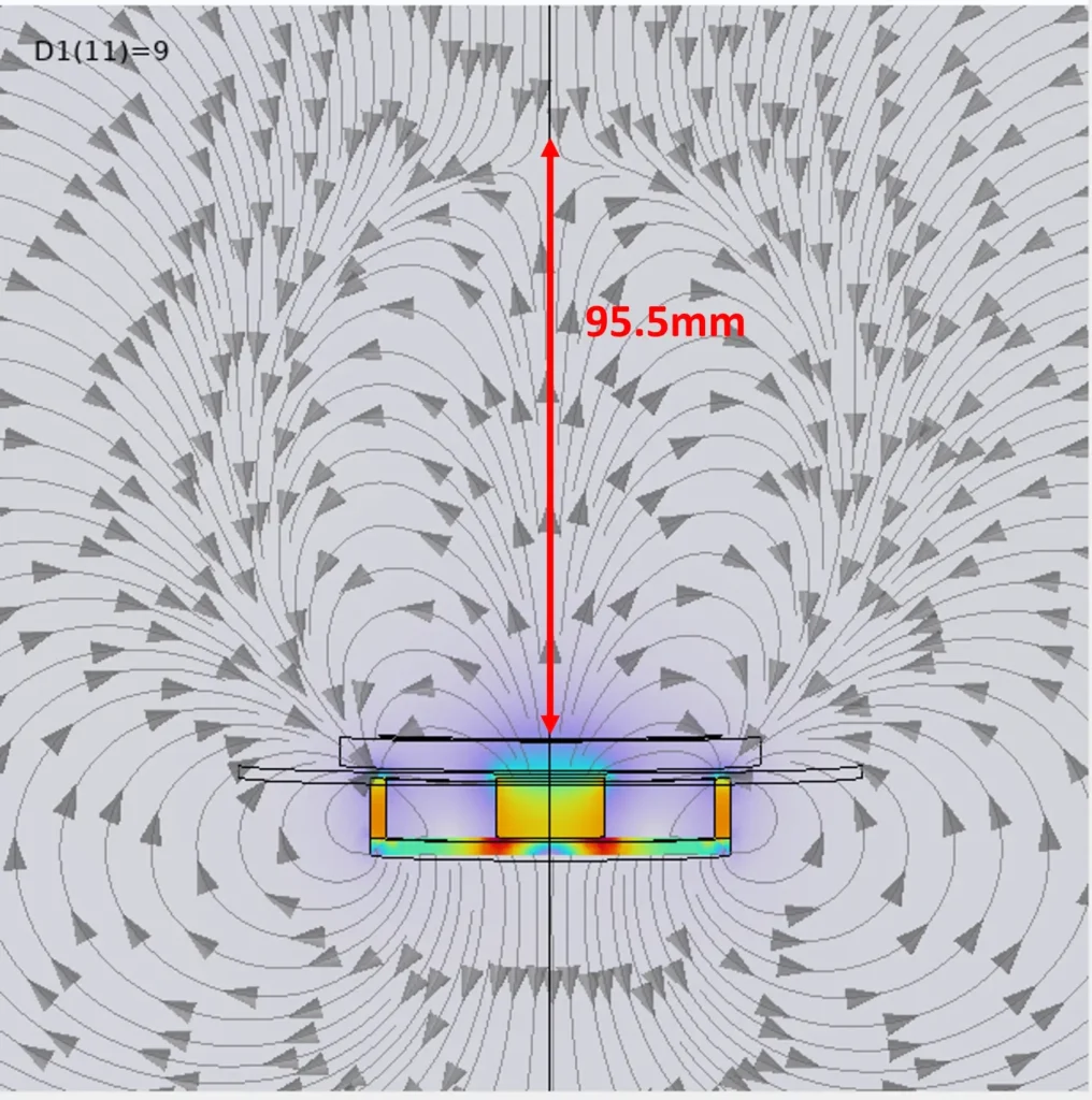
Figure 5. Cross-sectional magnetic-field plots for the five yoke-backed configurations, with the axial null height marked in each panel. Colour shading is qualitative.
What Does KG Tell Us, And What Does It Not?
KG summarizes the null-point height relative to the racetrack size and is a convenient factor for tracking how a cathode changes as it is modified. It does not reveal the full field topology, the pole fluxes, or the ion current and energy at the substrate, and it does not directly predict hardness, adhesion, stress or deposition rate.
Using KG it as a comparative indicator within one design category, one can state the reference plane and racetrack definition, and study the field plots. To predict ion assistance at the substrate, measured substrate ion current or validated plasma simulation is more direct evidence.
Conclusion
- An unbalanced magnetron lets part of the field reach towards the substrate, so more plasma and ions arrive there than with a balanced design.
- Type II configurations (outer pole stronger) suit ion-assisted deposition, but the label alone does not fix ion flux or energy.
- KG = znull / (2 rrt) compares the null-point height with the racetrack diameter and is a handy tool within one design family.
- In our simulations, raising the central-to-outer magnet area ratio from 0.11 to 0.34 moved the null from 33.2 to 95.5 mm while the racetrack barely changed.
Vac Coat Magnetron Sputter Coaters
Magnetron cathodes used in Vaccoat sputter coaters utilize permanent magnets, which provide uniform and stable magnetic field for enhanced plasma maintenance. In Vac Coat, we are able to produce balanced and unbalanced magnetron cathodes to meet our customer demands for various layer deposition conditions.
Vac Coat Ltd. designs and manufactures thin layer deposition systems using methods like sputtering, physical vapor deposition and pulsed laser deposition. Vac Coat sputter coaters include single and multiple-cathode high vacuum sputter coaters (DST1, DST3, DST3-T, and DST2-T), and rotary pumped desk sputter coater (DSR1).
Vac Coat also offers hybrid systems for multi-purpose coating projects, including sputter and carbon coaters, DSCR and DSCT, as popular thin layer deposition systems for SEM sample preparation, electron analysis, and contact coating as in solar cells and battery fabrication. DSCT is also available with thermal evaporation option, DSCT-T, as a compact versatile desk high-vacuum coating system.
References
- Angstrom Sciences, “Unbalanced Magnetron Sputtering (UBMS) Plasma,” Photo Gallery. https://angstromsciences.com/media_gallery/unbalanced-magnetron-sputtering-ubms-plasma (accessed 27 October 2026).
- D. A. Golosov, “Balanced magnetic field in magnetron sputtering systems,” Vacuum, vol. 139, pp. 109–116, 2017. DOI: 10.1016/j.vacuum.2017.02.018
- J. T. Gudmundsson, “Physics and technology of magnetron sputtering discharges,” Plasma Sources Science and Technology, vol. 29, no. 11, article 113001, 2020. DOI: 10.1088/1361-6595/abb7bd
- P. J. Kelly and R. D. Arnell, “Magnetron sputtering: a review of recent developments and applications,” Vacuum, vol. 56, no. 3, pp. 159–172, 2000. DOI: 10.1016/S0042-207X(99)00189-X
- M. Komath, G. Mohan Rao, and S. Mohan, “Studies on the optimisation of unbalanced magnetron sputtering cathodes,” Vacuum, vol. 52, no. 3, pp. 307–311, 1999. DOI: 10.1016/S0042-207X(98)00304-2
- V. Svadkovski, D. A. Golosov, and S. M. Zavatskiy, “Characterisation parameters for unbalanced magnetron sputtering systems,” Vacuum, vol. 68, no. 4, pp. 283–290, 2002. DOI: 10.1016/S0042-207X(02)00385-8
- B. Window and N. Savvides, “Charged particle fluxes from planar magnetron sputtering sources,” Journal of Vacuum Science & Technology A, vol. 4, no. 2, pp. 196–202, 1986. DOI: 10.1116/1.573470
- B. Window and N. Savvides, “Unbalanced dc magnetrons as sources of high ion fluxes,” Journal of Vacuum Science & Technology A, vol. 4, no. 3, pp. 453–456, 1986. DOI: 10.1116/1.573904