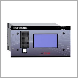
The radiofrequency (RF) generators provided by Vac Coat Company are reliable devices for industrial and laboratory deposition, plasma generation, and even dielectric heating and melting. RF signal generators are also one of the most important components of semiconductor manufacturing systems, used for producing integrated circuits (ICs) and chips present in modern computers and electronic equipment. The Vac Coat RF power generators accompanied by impedance matching network constitute a complete RF plasma generation assembly for RF sputtering and plasma treatment.
What is an RF Signal Generator?
RF generators are power sources that produce alternating current (AC) signals with high-frequency (In the range of radio frequency) by means of an oscillator circuitry, which is then amplified and tuned through RF generator tuning network. RF signal generators have multiple applications in research, testing, and calibration of RF-based electronic systems. RF power generators also play a crucial role in manufacturing electronic components and devices such as radios, televisions, and cell phones.

Main RF Generators Components
RF generators include several electronic parts to generate radio-frequency alternating current signals. These parts mainly include:
- The core of an RF power source and generates a stable sin wave signal with a specific frequency through a crystal oscillator or an LC (Inductor-capacitor) circuit
- The RF signal characteristics, such as amplitude, frequency, or phase can be modulated to optimize the performance and efficiency of the RF signal generator. Vac Coat RF power sources utilize a matching box or matching network that enables the adjustment of the frequency and impedance of the generated RF signal to maximize power transfer and diminish the reflected power. Vac Coat RF signal generators also enable the user to adjust the output power of the signals with high accuracy and stability
- Amplifier and Filter. The RF signal is boosted to achieve the preferred power level through the amplifier. The wave filters will eliminate signals with unwanted frequencies to enhance optimal performance
- Monitoring Interface. An intuitive user interface empowers precise control over the parameter adjustment and performance of the RF power generator. Vac Coat RF generators are supplied with an intuitive control panel for user-friendly workflow and real-time monitoring to optimize the functionality

The Matching Network Role in RF Plasma Generators
The radio frequency generators frequency and the chamber frequency should be matched to prevent damaging the sample or the RF power generator. This is the crucial role of the RF matching (Tuning) network to match the impedance of the chamber to the RF generator to lower the reflective power, dangerous radiation emissions, and RF noise that interferes with other electronic devices’ signals. The frequency of the RF generator can be modulated through varying the inductance and capacitance to match to the chamber’s frequency.
RF Plasma Sources in Vac Coat Sputter Coaters
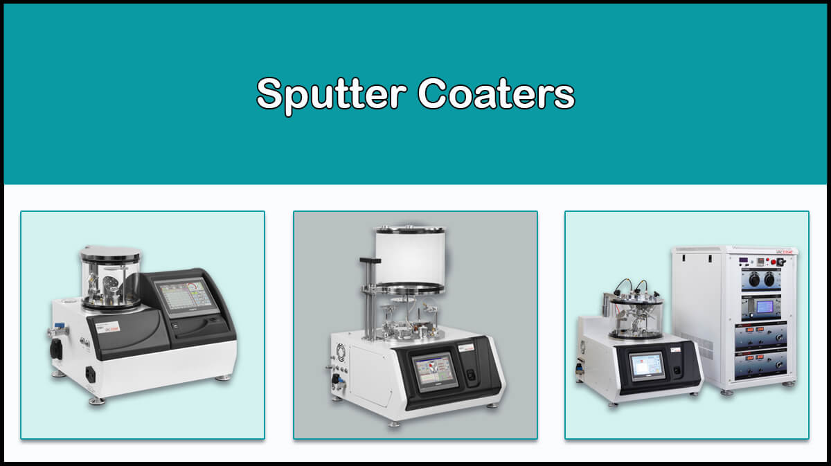
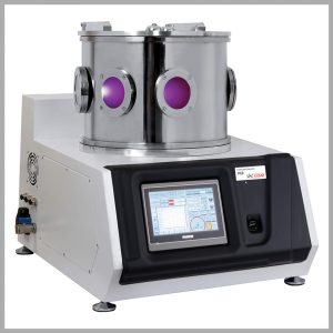
Vac Coat company employs RF plasma sources in its sputter coaters to perform RF sputtering for deposition of thin films of semiconductor targets like ZnO, SiO2, etc. RF plasma prevents charging effects of non-conductive surfaces during ion sputtering by applying alternating voltage to the cathode, which provides stable plasma generation and coating.
All Vac Coat large chamber sputter coaters such as DST1-300, DST3, DST3-T, and DST2-TG are able to be equipped with RF ion sources to deposit semiconductor thin films.
Why Using 13.56 MHz Frequency?
The RF generators are designed and built with 13.56 MHz frequency band according to the international standard radio bands commonly used in the industrial, scientific, and medical (ISM) applications, allowing high-power activities without causing any disturbance in the surrounding telecommunication systems. However, the RF generators can be delivered with 27.12 MHz, 13.56 MHz, 2 MHz or other frequency bands according to the customer.

Choose the Right RF Signal Generator
Vac Coat RF generators are offered in models with different powers, ranging from 100W to 15kW, with simple manufacture and setup procedure, along with safety features against electromagnetic interference, continuous operation capability, ease of operation and control and a touch screen or digital display.
Features of RF Generator
- Reflected power limiter by RF matching network
- Air-cooling (DC to RF conversion efficiency larger than 70%)
- Graphical control, display and adjustment system with a touch screen
- Various protection types (Against reflected power, over-temperature, overcurrent, and overvoltage)
- Capable of automatically limiting the transmitted power
- 0-5 V input voltage for remotely controlling the generator output power (Optional)
- More than 90% efficiency for larger than 300 W models
- Analog output for transmitted and reflected power values
- Closed-loop control of output power which stabilizes the adjusted power with time
- Adequate shielding to prevent radiation and EMI noise with necessary measures to protect operator health
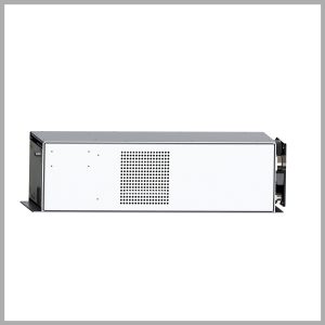
- Rack-installable box
RF Power Generators Applications
RF signals can be utilized in many areas from edge of science to industry applications. RF generators are mainly used in:
- Telecommunication
- Semiconductor production
- Medical treatment and healthcare, as in Magnetic Resonance Imaging (MRI) devices
- Physical and chemical plasma deposition
- Plasma etching
- Various plasma processing techniques (You can read more about vacuum plasma treatment)
- Heating and melting discarded dielectrics
- Testing and calibration
Specifications of RF Plasma Generators
| Power supply | 220 V (200-240 V), 50 Hz (50-60 Hz) |
|---|---|
| Output frequency | 13.56 MHz |
| Protection | Various types (protection against reflected power, over-temperature, overcurrent, and overvoltage), especially reflected power limiter |
| Display | Graphic display with touch screen or digital display |
| Remote control | Digital RS485 |
| Working temperature | 10-40°C |
| Cooling | Air conditioned |
| Output impedance | 50Ω (resistive) |
| Dimensions (cm) | Depends on device output |
| Weight | Depends on device output |
| Output connector | N – 7/16 |
| Box material | Aluminum |
RF Generators Models
| RFG200 | RFG300 | RFG600 | RFG1000 | RFG2000 | RFG5000 | |
|---|---|---|---|---|---|---|
| Frequency (MHz) | 13.56 | 13.56 | 13.56 | 13.56 | 13.56 | 13.56 |
| Power (W) | 200 | 300 | 600 | 1000 | 2000 | 5000 |
| Output impedance (ohms) | 50 | 50 | 50 | 50 | 50 | 50 |
| Connection type | Analog & Digital max485 | Analog & Digital max485 | Analog & Digital max485 | Analog & Digital max485 | Analog & Digital max485 | Analog & Digital max485 |
| Front panel display | LCD | LCD | LCD | LCD | 7segment | 7segment |
| Output connector | N | N | N | N | N | 7/16 |
| Touch screen | Yes | Yes | Yes | Yes | No | No |
| Input power | Single-phase | Single-phase | Single-phase | Single-phase | 3phase | 3phase |
| Cooling | air-cooled | air-cooled | air-cooled | air-cooled | air-cooled | air&water-cooled |
Some of Our Products
References
- https://vactechniche.com/rf-generator-comp/?srsltid=AfmBOop_jXrtXPaCfZOESdbiwXNGWSd2QjeO_0JuP7AE9NXu0QIpQKJh
- https://vactechniche.com/rf-generator/?srsltid=AfmBOorn0KGaK3DLgBGu1kPHRJST0WVZaI9QAXsJlLGGunKuampVFXVU
- https://www.keysight.com/used/us/en/knowledge/guides/signal-generator-buying-guide/what-is-a-rf-signal-generator
- https://www.semigroup.com/radio-frequency-rf-generators/
- https://www.rfpage.com/rf-signal-generators-types-and-applications/
FAQ
Is RF Signal An AC or DC Signal?
RF or Radio frequency is the rate of oscillation of an alternating electric current (AC) or voltage of a system.
What is the range of frequencies in RF signals?
The frequency in this region could be in the range of 20 to 300 GHz.
What is the matching network in the RF signal generators?
RF matching network or RF tuning network in a RF plasma source is required to change the equivalent impedance of the system according to the amount of generator impedance in order to prevent the reflection of the power transmitted by the generator, protect the RF generator, maximize the power input to the load, enable repeatable processes, and provide the necessary field intensity for the plasma formation in the chamber.


