
What is Pulsed DC Sputtering?
Pulsed DC Magnetron Sputtering is a physical vapor deposition method used to make thin films of various materials including conductors and insulators. It is especially preferable in reactive ion sputtering where the risk of arc discharge damage is high. The arc discharge is a result of charge accumulation on the target and is harmful to both the thin film and the power supply.
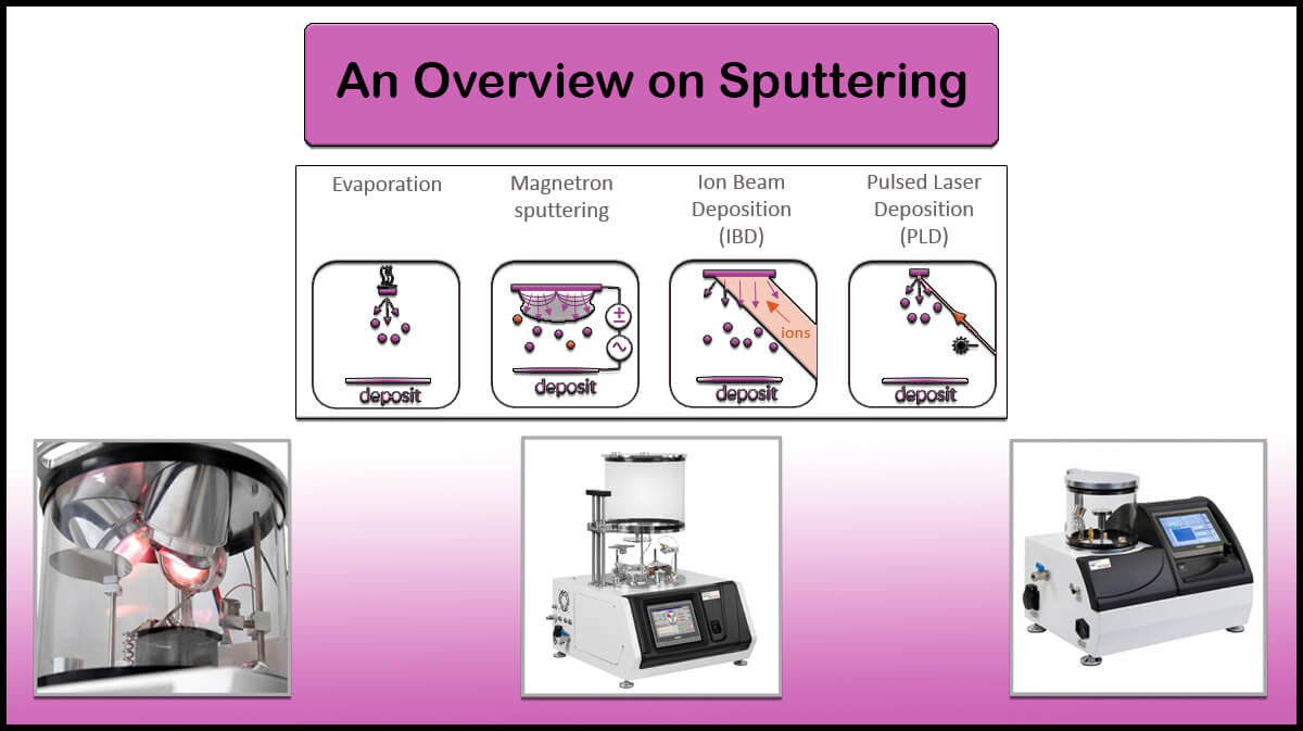

As a simple and reliable vacuum deposition technique, Sputtering is one of the most common techniques for thin films deposition methods today. In a typical sputtering process, accelerated ions from the plasma knock the atoms out of the target material. The emitted particles with certain kinetic energy are directed toward the substrates’ surface.
The power supplies used in magnetron sputtering can be categorized as DC, RF, Pulsed DC, and HPIMS. In the following, we outline a brief explanation that shows the differences between these types of power, (Figure 1).

Pulsed DC Magnetron Sputtering
Pulsed DC Magnetron Sputtering with a variable frequency range of 40 to 200 kHz is widely used in reactive sputtering applications in two common forms of unipolar pulsed sputtering and bipolar pulsed sputtering. In the pulsed DC magnetron sputtering process, by the collision of positive ions, a positive charge accumulates on the surface of the target material. So, it results in a decrease in the tendency of positive ions towards the target material.
Pulsed DC magnetron sputtering can be divided into two common forms: unipolar pulsed sputtering and bipolar pulsed sputtering. The unipolar pulsed sputtering method is based on the induction of a positive voltage at some frequency on the power waveform to clean the target surface and eliminate the accumulation of a dielectric layer.

The bipolar pulsed sputtering is based on the two pulses (180-degree out-of-phase) applied to the magnetrons. Each magnetron alternates as a cathode and anode to reduce any effect due to the dielectric accumulation. As shown in Figure 2, in pulsed DC sputtering, power is applied to the target material at ton, which is called “on time”. At this time, a negative voltage (a few hundred volts) is applied to the target material, and at the end of this time, the voltage switch to a positive pole with a smaller amplitude (about 20 volts). The “reverse time” (trev) is the polarity inversion of the voltage applied.

The surface of the dielectric material is charged in “on time”, and is discharged in the “reverse time” period. The “on-time” should be short enough that the charges on the surface cannot arc during this time interval, and on the other hand, the “off-time” should be long enough that the sorted charges on the surface to be completely discharged, to prevent the charge accumulation in sequential “on” and “reverse” cycles.
The duration of plasma formation and stabilization depends on several factors, including pulse duration, pulse frequency, power, and pressure. In pulses with shorter lengths and higher frequencies, the plasma accumulation phase is predominant and the pulsed magnetron sputtering operates in voltage mode. At longer pulses and at lower frequencies, the stationary plasma phase is predominant and the pulsed magnetron operates in the current mode. At constant current mode, a high voltage rapidly accelerates the ions toward the target and re-establishes the current and the deposition rate.

DC Magnetron Sputtering
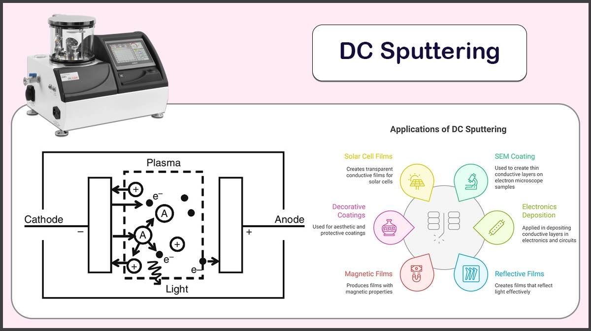
DC sputtering is based on a direct current (DC) power source, and the chamber pressure is usually from 1 to 100 mTorr. The positively charged ions are accelerated towards the target material and the ejected atoms deposit on the substrates, (Figure 3). This technique is generally used with pure metal sputtering materials such as Iron (Fe), Copper (Cu), Nickel (Ni) with a high deposition rate. This process is easy to control and has a low cost of operation for processing large substrates.
The DC sputtering of dielectric materials causes the wall of the vacuum chamber to be coated with a non-conducting material which can trap electric charges. In this regard, the small and macro arcs appear during the deposition process, which causes uneven remove of atoms from the target material. These arches can also damage the power supply.

RF Magnetron Sputtering
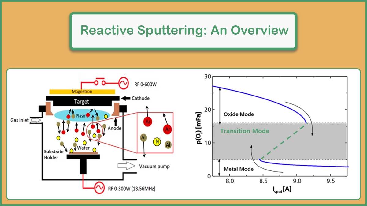
RF sputtering or Radio Frequency is based on an AC (Alternating Current) source with the chamber pressure from 0.5 to 10 mTorr, and a 13.56 MHz power supply. RF power supplies can be used with all materials as conductive and non-conductive, however, most have been proposed to prevent problems caused by the DC sputtering of dielectric materials.
The RF sputtering involves two processes. In this mechanism, the target material and the substrate holder act as two electrodes. Electrons oscillate at the applied frequency between the two electrodes. In the positive half-cycle, the target material acts as an anode and attracts electrons. Because of the difference in the mobility of electrons and ions in a plasma, the ions remain at the center of the two electrodes. In this regard, the electron flux on the substrate is much higher and may cause significant heating. The polarization makes the target atoms and ionized gas remain on the target surface.


In the negative half-cycle, the target is positively charged and acts as a cathode. By making a reverse polarization, the gas ions and target atoms ejected and accelerated toward the substrate to make deposition of the film.
In the RF sputtering method, the power is divided between the two electrodes, so the effective power at the target material is 50% of the power applied in DC sputtering. As a result, the RF sputtering rate is lower than the DC sputtering. Also, due to the high cost of RF power supplies, and their impedance matching boxes and complexity, the use of RF sputtering is not very welcome and it is mostly used for smaller substrate sizes.
High-Power Impulse Magnetron Sputtering
In October 2001, a method called High-Power Impulse Magnetron Sputtering (HPIMS) was introduced that won the US patent award. It is an emerging process that uses a high power (100 times higher than conventional power) to greatly increase the ionization of the sputtering material. This high ionization plasma results in a more uniform film deposition.
The ionized atoms have much higher energies than sputtered atoms in conventional magnetron sputtering and have been found to yield very dense and stable films. The thin film deposited by this method will have a high density. For example, the reported density for the carbon thin film deposited by HPIMS is 2.7 g / cm3 while the reported density for the thin film deposited by DC magnetron sputtering is 2 g/cm3.

Vac Coat Sputter Coaters
Vac Coat Ltd. is known for designing and manufacturing high-quality and reliable vacuum coating systems. All VacCoat Sputter Coaters are able to deposition by pulsed DC magnetron sputtering method (This is optional and should be mentioned when ordering if needed). The Sputter Coaters include desk sputter coater (DSR1), sputter coater with a thermal evaporator (DST3 & DST3-T), magnetron desk sputter coater (DST1-300 & DST1-170), turbo pumped desk sputter with carbon coater (DSCT & DSCT-T), and desk sputter and carbon coater (DSCR & DSCR-300), suitable for sputtering depending on the desired material (oxidizing or non-oxidizing). For more information refer to the website.


References
- Sputtering Sources, Matthew M. Waite, West Chester University of Pennsylvania, West Chester,Pennsylvania; S. Ismat Shah, University of Delaware, Newark, Delaware;David A. Glocker, Isoflux Incorporated, Rochester, New York
- Pulsed magnetron sputtering – process overview and applications, P. J. KELLY, J. W. BRADLEY, JOURNAL OF OPTOELECTRONICS AND ADVANCED MATERIALS, Vol. 11, No. 9, September 2009, p. 1101 – 1107
- Characterization of pulsed dc magnetron sputtering plasmas, A Belkind, A Freilich, J Lopez, Z Zhao, W Zhu and K Becker, New Journal of Physics 7 (2005) 90, doi:10.1088/1367-2630/7/1/090
- http://www.semicore.com/news/92-what-is-rf-sputtering
- https://www.aemdeposition.com/sputtering-targets-news/dc-sputtering-vs-rf-sputtering.html