Thickness Uniformity of Thin Films by Magnetron Sputtering
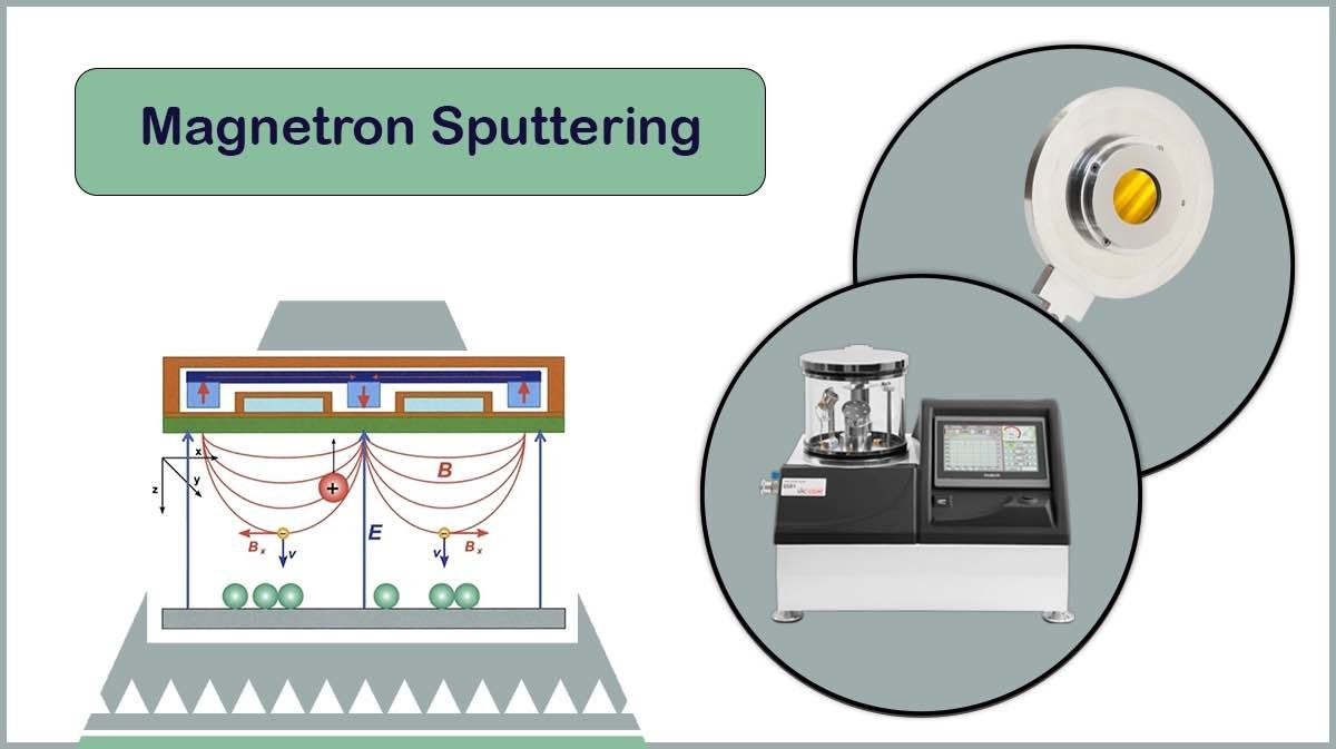
Magnetron Sputtering is a highly advantageous method for depositing thin films of materials on a substrate for research and industrial purposes. Thickness Uniformity of thin films is an important parameter in science and industry, which can be obtained by magnetron sputtering to a high degree of precision (<2% of thickness variation over the substrate) [1]. Vac Coat Sputter Coaters can sputter materials by magnetron sputtering method through precise control over chamber pressure, source to substrate distance, and substrate rotation to enhance thickness uniformity of the coated film.


Why Uniformity Matters?
Producing a uniform thickness of PVD coatings is of great importance, since it determines the performance, durability and quality of the final product. In optical coatings, the smallest change in thickness can change the light transmission or reflection properties. In the semiconductor industry, layer uniformity is essential to ensure conductivity or insulation. Mechanically, non-uniform layers lead to stress, cracking or delamination. In protective coatings, thin spots can also be the starting point for corrosion or wear. Also, in decorative applications, thickness variation causes color and appearance changes. Therefore, thickness uniformity is critical for stable performance and coating longevity.
What Affects Film Thickness Uniformity in PVD Coatings?
Some processes during deposition affect thickness uniformity of the resulting layer in magnetron sputtering. Based on theory, the uniformity of thin-film thickness deposited by magnetron sputtering can be managed by considering the effects of geometric parameters such as:
- Target-substrate distance
- Ion energy
- Target shape
- Size and erosion pattern
- As well as, substrate temperature
- Eccentricity and rotation
- Chamber pressure

Target Erosion and Shape Effect
Target Erosion
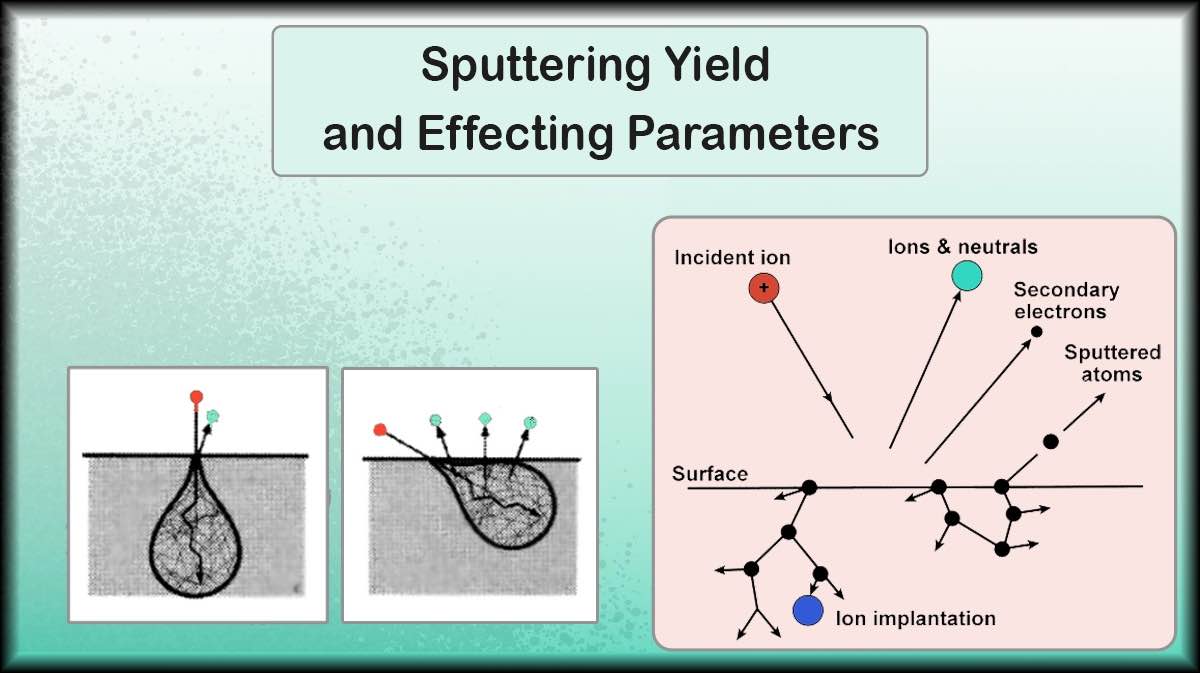
Target surface homogeneity influences uniformity of deposited layer. Charged particles created as a consequence of ion bombardment of target, tend to swirl above the target in the presence of magnetic field of the magnetron cathode, then undergo collisions with argon atoms and produce more free electrons and positive Ar ions. Charged particles confined to the target surface by the magnetic field collide with the target, where erosion occurs (Figure 1).
Magnetic confinement of energetic electrons in magnetron sputtering increases ionization and sputtering rate at lower operating pressure and higher deposition quality, while suffers from drawbacks such as non-uniform ion flux onto target, non-uniform target erosion, and reduced target utilization (Typically 20-40%).
According to the uneven erosion of the target, the sputtered target atoms originate from a restricted area, which affects their spatial distribution.
Target Shape
The target shape affects the uniformity of deposited layer thickness distribution resulting from the sputtered particles spatial distribution.
In general, film thickness distribution, T in magnetron sputtering systems is proportional to the growth rate at each point of the substrate.
The film thickness distribution on a substrate over a round target is formulated in Equation 1:
![]() Equation 1
Equation 1
Where c2= a2+b2, b2= R2+r2-2Rrcosφ. Geometrical parameters are shown in Figure 2 (Left), cosn(θ) characterizes spatial distribution of the flow of sputtered atoms and Ψ(R) describes cathode erosion rate [4].
Also, the uniformity of the deposited thin film from a rectangular target with different target-to-substrate distances is shown in Figure 2 (Right).
Chamber Pressure Effect: Thickness Distribution Due to Fast and Slow Particles
The sputtered species from the target surface are divided into fast and slow particles, according to the chamber pressure during the magnetron sputtering process.
Rapid particles reach the substrate surface directly without any impact after sputtering, while slow particles arrive the substrate surface by diffusion with successsive scattering.
Equations 2 and 3 below show the number of fast particles and the number of slow particles deposited per unit area on the substrate.
Where Yt is the number of particles scattered per unit area of the target, (xt, yt) the coordinates of a point on the target, and κ is the diffusion coefficient (m^2/s).
In the total thickness, we must consider both fast and slow particles. From Equations (2) and (3), it can be seen that the uniform distribution of layer thickness is affected by geometric parameters: target-substrate distance, temperature, gas pressure, the electromagnetic force, and other factors. For the target, it is important to define the geometric parameters of the erosion area, as they directly determine the overall thin film deposition process. To simplify the model, the following hypotheses are necessary:
Impact of Target-to-Substrate Distance on Thickness Uniformity
Generally speaking, increasing the target-substrate distance results in a more uniform deposition according to the more uniform spatial distribution of sputtered target atoms.

Case Study: Coating Uniformity from a Rectangular Target
To investigate the dependence of thickness uniformity on target-to-substrate distance and target erosion area for a rectangular target, assuming copper as the target material and argon as the sputter gas, the energy of dispersed copper atoms is less than 10 eV. Therefore, the free mean path for copper atoms is equal to:
λcu=3.45×10^(-4)×(T/P)
For a temperature of 300 K and a pressure of 1 to 5 Pascals, the free mean path of copper atoms is 21 to 138 mm.
The Length percentage is assumed as the ratio between the length of uniform area on the substrate and the substrate length to verify the thin film thickness uniformity under different target conditions, and the uniform area is defined as the area where the thin film thickness has less than 5% non-uniformity.
Changing of the target-to-substrate distance from 30 mm to 80 mm with the sputtering yield (Y) as 1.5 atoms per ion, current density of 2 mA/cm2, and the mean free path of the copper atom of 40, 60, and 80 mm, the percentage of uniform length decreases accordingly. As a result, the thickness of the thin film increases with decreasing target-substrate distance (Figure 3). The beta factor in this chart is the fitting factor.

As shown in Figure 4, sputtering power and working pressure influence on the deposited film thickness distribution are investigated.
Substrate Motion
Moving the substrate during the deposition process can redistribute the particles over the substrate. Substrate rotation is typically used to improve the uniformity of the deposited film, even on substrates with areas much larger than the target.

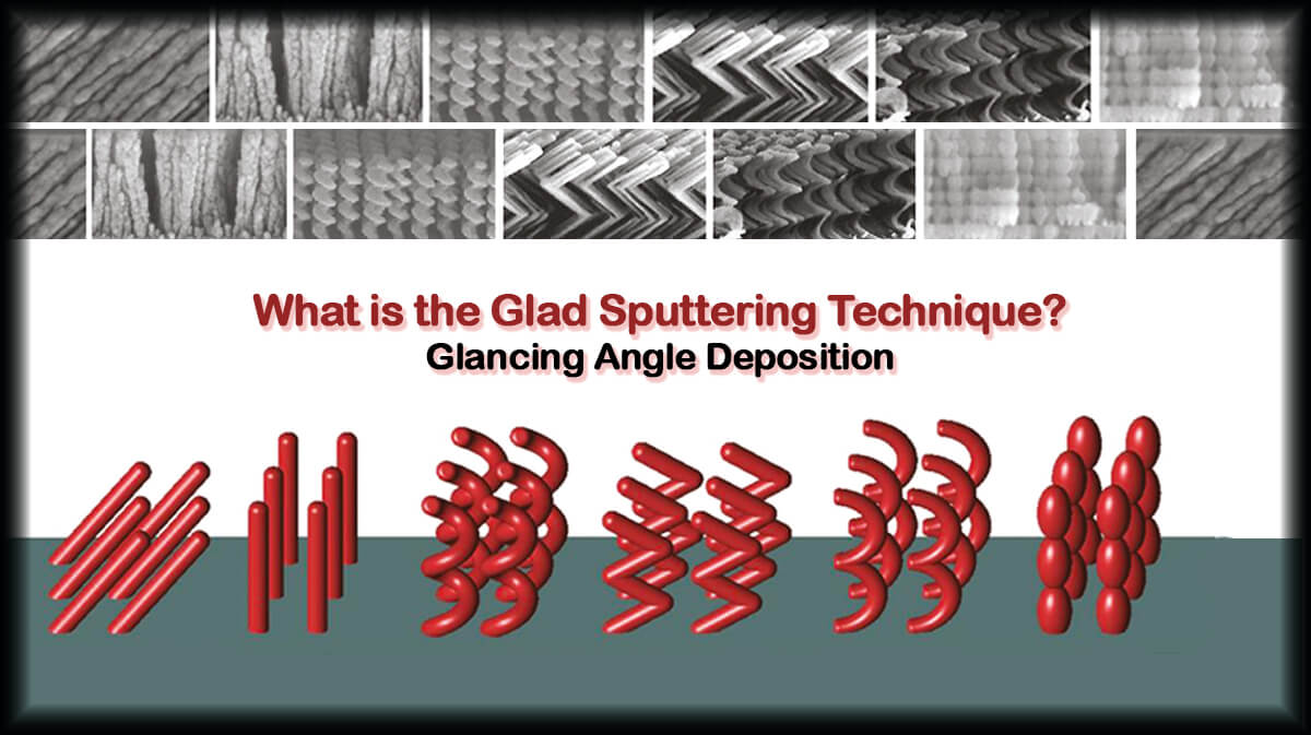
Substrate rotation can perform in various types, such as planar motion, planetary rotation, or angled rotatory motion. Every rotation type results in a distinct deposition uniformity and can result in formation of different structures.
Vac Coat vacuum coaters can be equipped to different rotation stages to rotate the substrate during the coating process. Sample rotation stage with adjustable height and tilt is supplied with Vac Coat sputter coaters and carbon coaters. Vac Coat also offers planetary sample rotation stage that enables GLAD sputtering and more uniform coating over small (Diameter up to 2 inches) substrates.
Substrate Eccentricity
The eccentricity of the substrate related to the target is defined as the shift distance between the centre of the target and the substrate as in Figure 6.
The deposition rate V (r2, t) at the time t of the substrate surface point situated at the distance r2 from the substrate center can be calculated by Equation 4.
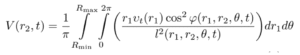 Equation 4
Here, Rmin and Rmax are the minimum and maximum radii of erosion area; ϕ is sputtering and condensation angle; θ is the polar angle; l is the distance from the sputtering point to the deposition point; and v1(r1) is the sputtering rate of the target material in the radius r1, as depicted in Figure 6.
The profile of the thickness distribution at different shift of the substrate center relative to the target center shows that with increasing distance between the substrate and target centers, the deposition rate decreased, but the uniformity of the layers increased simultaneously.
Vac Coat DSCT-300 with double sputter and carbon coater lid can enable shifted substrate holder centre relative to the source to enhance coating uniformity.

Masking the Target
Masking the target surface with different patterned covers can also control the deposition rate from source points onto the substrate, enhancing the thickness uniformity of the resulting coating. The change in the thickness uniformity of thin films resulting from utilizing a mask is displayed in Figure 7.
The model DST3-S sputter coater with triple straight cathode can be supplied with a specially designed mask to improve film thickness uniformity.


Thickness Uniformity in Our Sputter Coaters
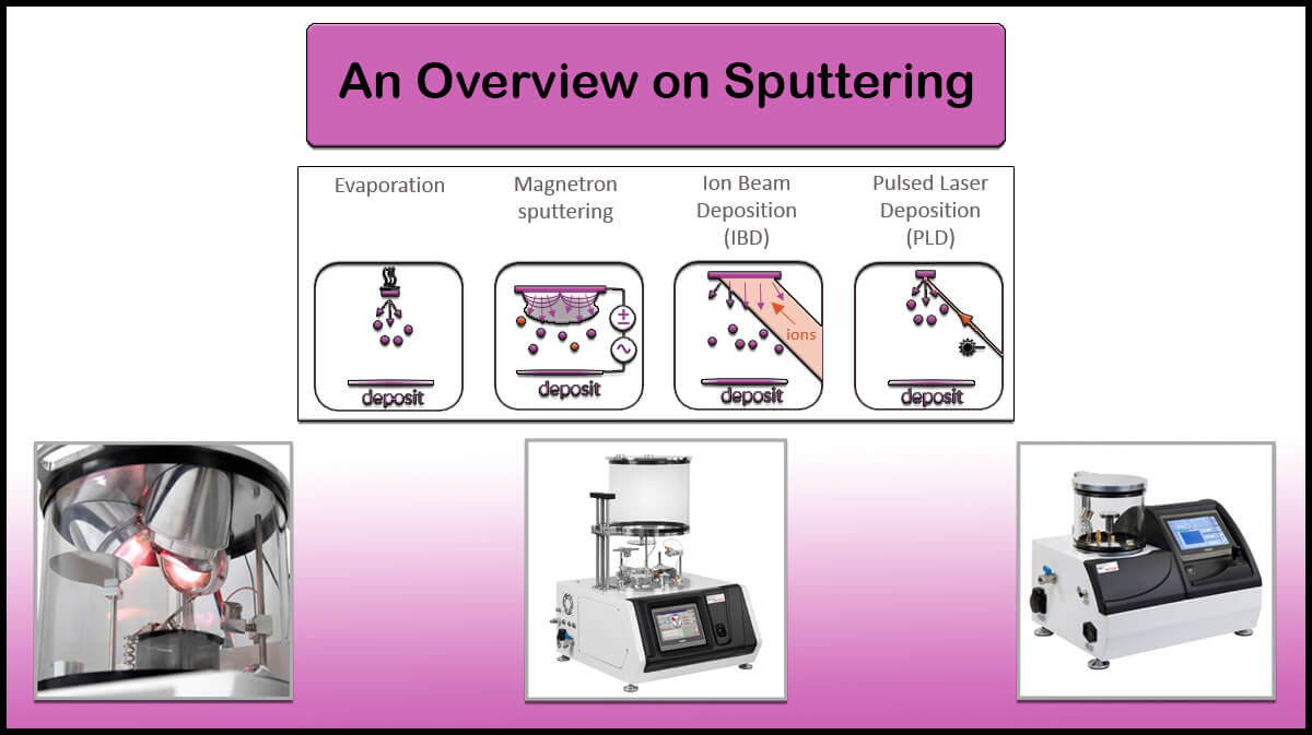
Vac Coat Ltd. is known for designing and manufacturing high-quality and reliable Physical Vapor Deposition and vacuum coating systems. Its products include sputtering systems, carbon coating systems, thermal evaporation systems, and pulsed laser deposition system. All Vac Coat Sputter Coaters are able to deposition by magnetron sputtering method and some of them can create Cu thin films by DC Magnetron Sputtering.
The Sputter Coaters include sputter coater with a thermal evaporator (DST3 and DST3-T), magnetron desk sputter coater (DST1-300 and DST1-170), and turbo pumped desk sputter and carbon coater (DSCT and DSCT-T), that equipped by turbomolecular pump.
Related Posts


Some Of Vac Coat's Products


References
- M. Geisler, Ch. Braatz, J. Bruch, A. Kastner, M. Kress, M. Ruske, T. Willms, A. Zmelty, Meeting the demands of modern large area glass coating: latest developments of horizontal and vertical coaters and applications, Thin Solid Films, Volume 442, Issues 1–2, 2003, Pages 15-20, https://doi.org/10.1016/S0040-6090(03)00931-3
- Performance of a size-selected nanocluster deposition facility and in situ characterization of grown films by x-ray photoelectron spectroscopy,Review of Scientific Instruments 85, 065109 (2014) http://dx.doi.org/10.1063/1.4882315
- Feist, Christian, A. F. Plankensteiner and Jörg Winkler. “Studying Target Erosion in Planar Sputtering Magnetrons Using a Discrete Model for Energetic Electrons.” (2013).Proceedings of the 2013 COMSOL Conference in Rotterdam
- Soloviev, A. A., N. S. Sochugov, K. V. Oskomov, and N. F. Kovsharov. “Film thickness distribution in magnetron sputtering system with the round cathode.” Изв. вузов. Физика 8 (2006): 491-493.
- Coatings 2021, 11, 599. https://doi.org/10.3390/coatings11050599
- ZHANG Yichen et al. / Physics Procedia 32 ( 2012 ) 903 – 913
- Golosov, D., Melnikov, S., Zavadski, S., Kolos, V., & Okojie, J. (2016). The increase in thickness uniformity of films obtained by magnetron sputtering with rotating substrate. Plasma Physics and Technology, 3(3), 100-104.
- Z. Jiang, J.Q. Zhu, J.C. Han, P. Lei, X.B. Yin, “Uniform film in large areas deposited by magnetron sputtering with a small target”, Surface and Coatings Technology, Volume 229, 2013, Pages 222-225, ISSN 0257-8972, https://doi.org/10.1016/j.surfcoat.2012.03.075.
- Wang, Ben, et al. “Simulation and optimization of film thickness uniformity in physical vapor deposition.” Coatings 8.9 (2018): 325.