
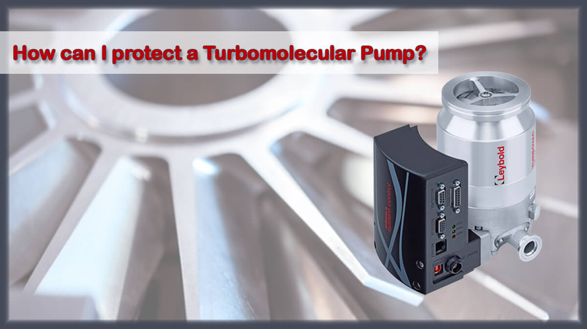
Learn More About Turbomolecular Pumps
One of the most commonly used pumps for high vacuum pressure is the Turbomolecular Pump. These pumps are easy to use, require less care and maintenance, as well as less contamination, which is desired in clean than other pumps to reach high or ultra-high vacuum, such as diffusion pumps.

Turbomolecular Pump Uses
Turbomolecular pumps can be used in the range of rough vacuum, high vacuum and Ultra-High Vacuum (UHV) with a constant pumping speed of up to 4000 liters per second. Turbomolecular pumps are kinetic vacuum pumps that operate using a very fast rotor (usually between 24,000 and 350,000 rpm), which can provide from high vacuum to ultra-high vacuum condition. Employing oil-free turbomolecular pumps merits a cleaner vacuum chamber is critical in processes that require a completely clean vacuum environment.
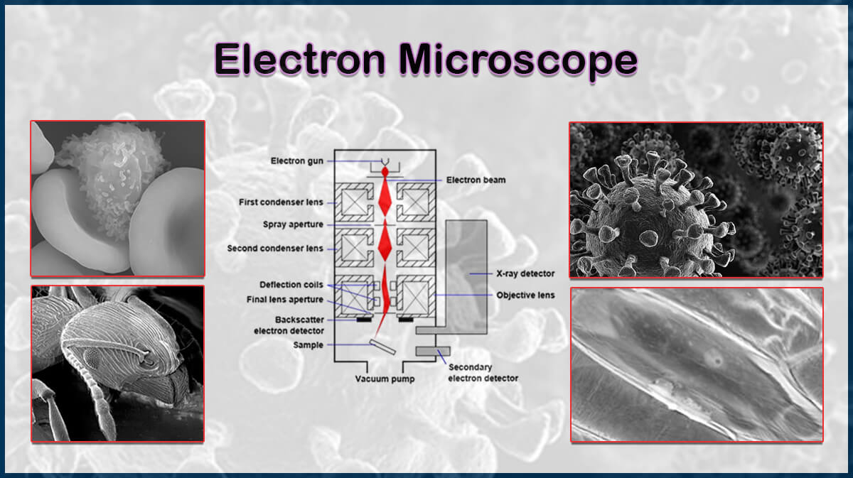
These features mean that turbomolecular pumps are suitable for a wide range of applications, from Electron Microscopes to semiconductor processing, some listed below:
- Coating systems
- Ion implantation systems for semiconductor doping
- Mass Spectroscopy
- Wafer bonding systems
- LCD displays production
- etc…
Turbomolecular Pump Vacuum Range
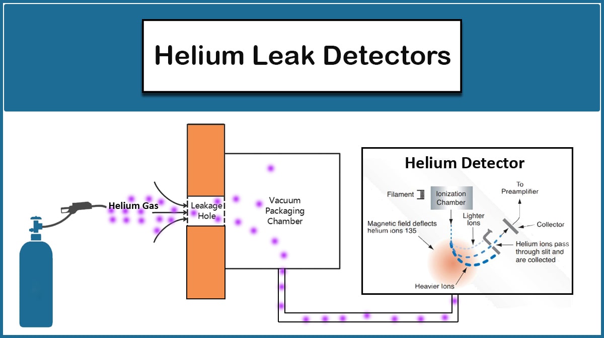
Typical characteristics include pumping speeds of ranging from 50 to 3000 liters/s and ultimate pressures below 10-8 mbar. In order to reach 10-6 to 10-8 mbar, chamber conditioning by venting it with a dry venting gas, like nitrogen, and baking out can help. To achieve pressure ranges below 10-8 mbar, additional pre-conditions should be satisfied, including choice of proper pump possessing the required compression ratio, using metal seals and CF flange connections, baking out the pump and apparatus, vacuum leakage detection and elimination using helium leak detectors, using clean gloves in the assembly process, using dry venting gas in ventilation process.

Turbomolecular Pump Vs Diffusion Pump
Turbomolecular vacuum pumps has several advantages, including:
- Small footprint
- No need to water-cooling
- Fast vacuuming cycles
- Low contamination
- Good accuracy with nearly constant pumping speed
One of the disadvantages of turbomolecular pumps is their high price.

Vac Coat offers high-vacuum DTE and DTT desk thermal evaporators optimized for the deposition of different materials’ thin films by thermal evaporation methods.
Vac Coat company offers different carbon coaters and hybrid sputter & carbon coaters suitable for electron microscopy sample preparation and research purposes.
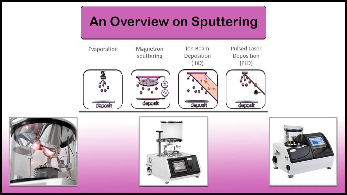
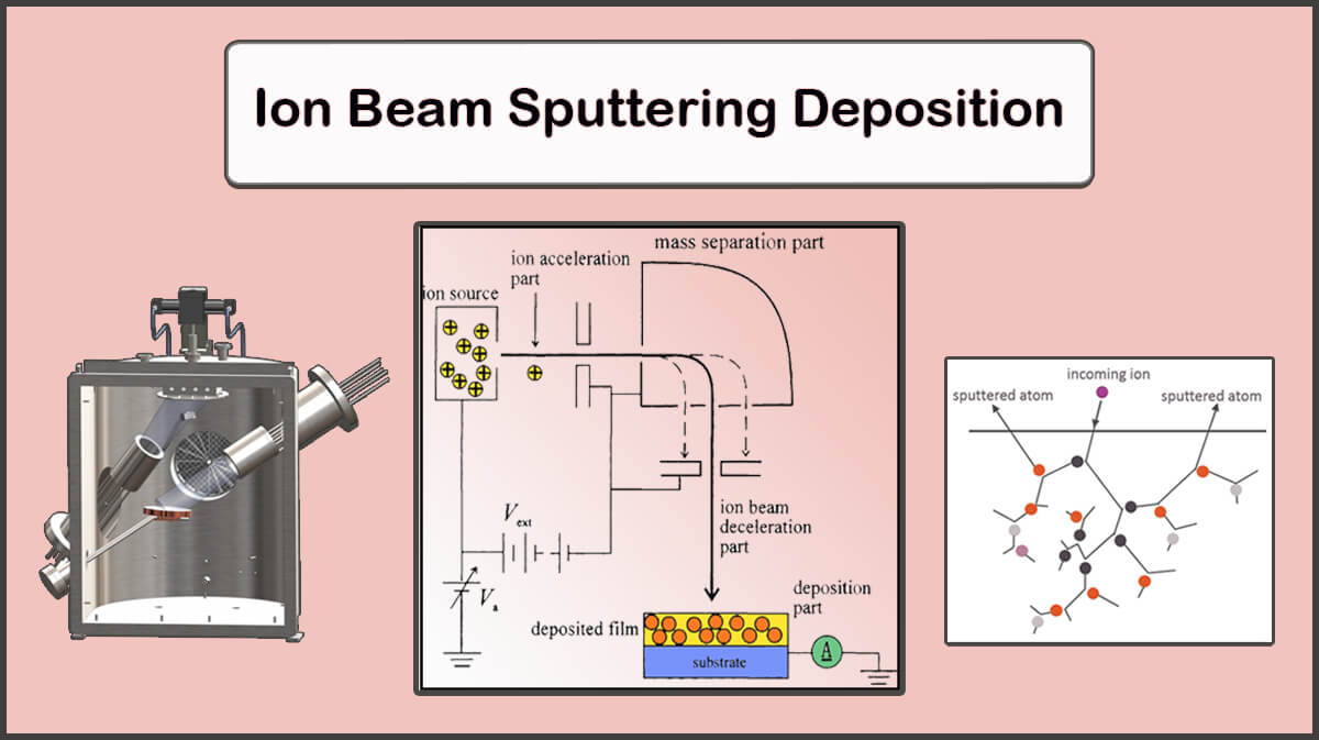
Vac Coat Ltd. produces and designs different types of sputter coaters systems. Sputtering is a method to deposit thin films of various materials on a substrate.


Turbomolecular Pump Working Principle
The turbo pump was invented in 1957 by W. Becker based on old molecular traction pumps invented by Wolfgang Guide in 1913, named after its resemblance to a turbine in the structure. Turbomolecular pumps work based on guiding the gas molecules in the desired direction by repeatedly colliding with a moving metal blade (Figure 1). In a turbomolecular pump, a rapidly rotating fan collide the gas molecules to create or maintain a vacuum, directing them from the pump inlet to the exhaust.

Turbomolecular Pump Design
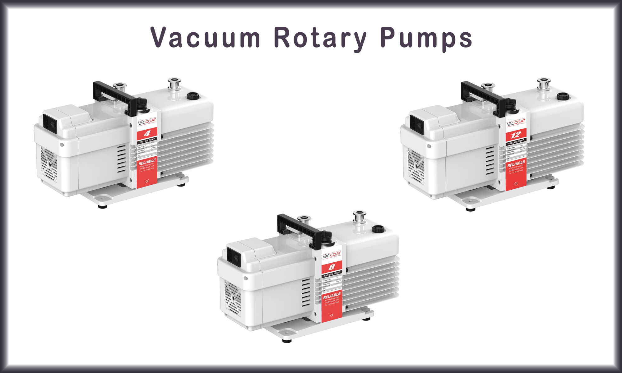
Turbomolecular pumps is made of a vertical axial-flow compressor containing several rotor/stator pairs or stages mounted in series. Gas captured by the upper stages is transferred to the lower stages where it is successively compressed to the level of the fore-vacuum pressure (Figure 2). The system works like a compressor that puts kinetic energy into the gas, rather than taking it out.


Figure 2. Schematics of a turbomolecular pump design.
The gas is transferred to the lower stages by the upper steps and is compressed successively to the vacuum pressure level of the backing pump. As gas molecules enter the input, the rotor, which has a number of angular blades, collides with the molecules. Because the compression of each step is approximately 10 times, each step closer to the output is significantly smaller than the previous input steps. The performance of the turbomolecular pump is strongly related to the rotor frequency (speed). The compression ratio varies exponentially with the product of the circumferential rotor speed and square root of the molecular weight of the gas.
As the speed increases, the rotor blades become more deflected. To increase the speed and reduce deformation, stronger materials and different designs are considered for blades. A blade for high pressure operation must be strong and stable and as thin as possible to be slightly bent for maximum compression.
To compress the gas from the lower pressure chamber toward the higher pressure environment, the dimensions of the pump channels should be designed in the range of mean free path length of the gas molecules.

How Does a Turbomolecular Pump Work?
When the gas molecules enter the turbopump, the mechanical energy of the blades is transferred to them. Due to the relative motion of the rotor and stator and special angles to each other, the gas molecules preferably hit the bottom surface of the blades. Therefore, the compressed molecules enter the gas transfer channels in the stator. Combination of a rotor and pair of stators (Or a rotor disk and a stator disk) constructs a pump stage that can create compression ratio of about 30 for air. This leads them to the next stage, where they collide with the surface of the rotor again, and this process continues, and eventually the gas molecules are driven out by the exhaust. The sequential pump stages magnify the compression effect of greater than 1012 for air.
The bearing rotors in a turbomolecular vacuum pump can be mechanical, magnetic, or a combination of both, which are described below:
Mechanical Bearing
Some models of Turbomolecular Vacuum Pumps use mechanical bearing rotors (Normally in a so-called cantilevered design with bearings at the lower end of the shaft and in the area of the lower rotor stages). Turbomolecular pumps must operate at very high speeds, and the heat generated by friction limits the design.
The high rotational speed of the turbo pump (some small diameter units operate at 60,000 rpm) puts serious pressure on the shaft bearings. The pumps involved in this method require lubrication, and the pump life depends on the bearing life. Since replacing the bearing is a specialized job, it must be done by opening the pump and sending it to the factory.
The grease and lubricant used in this method should not evaporate under the working pressure of the pump and cause the vacuum destruction. In addition, mechanical bearings make the rotor less dynamic than other types of bearings. Despite all the problems, mechanical bearings have high resistance to external shocks or sudden ventilation and also have small foot print.

Magnetic Levitated Bearing
One of the alternatives for mechanical bearings is active five-axis magnetic bearings (2X, 2Y, Z) located at both ends of the rotor shaft with position sensors and variable magnetic field control (Magnetic levitated bearings). In these magnetic bearings, which either use a permanent magnet for small pumps or a combination of permanent and dynamic magnetic fields, the shaft is contactless. Magnetic pumps include non-contact bearings in which the oil vapor is zero and the bearings do not wear out. Compared to mechanical bearings, these pumps do not require lubrication, causes a process free of hydrocarbons, the pump life is not limited to bearing wear out, and have very low vibration.
Due to the lack of mechanical bearings, corrosive gases can be used in environments evacuated by these pumps, which typically eliminate oil bearings in a short period of time. Pumps that use magnetic bearings are more vulnerable to external shocks compared to turbomolecular pumps that have mechanical bearings. In addition, they are larger and more expensive than pumps that use other types of bearings.
Hybrid Bearing
Another type of bearings used in turbo pumps is hybrid bearings. Hybrid bearings have mechanical bearings located at the bottom end of the shaft rotor and a pair of passive magnetic bearings located at the top end of the shaft. Unlike systems with two mechanical bearings, the lifespan of these units is mainly limited to the life of one mechanical bearing, and they also have less vibration due to the lack of a second mechanical bearing.
Like all-magnetic turbomolecular pumps, hybrid-bearing pumps are less tolerant of external shocks and are slightly larger than systems with two mechanical bearings. The design of the hybrid bearing is such that it causes the desired dynamics of the rotor and also allows the bearing to be replaced on-site.

Corrosive Turbomolecular Pumps
Utilizing turbo pumps under harsh conditions, such as pumping out corrosive gases, the bearing area and the rotors should be properly designed to protect them against corrosion. This can be done by coating the surfaces that come into contact with the gas with a resistive thin film.

Turbomolecular Pumps in Vac Coat Products
This article has briefly reviewed the turbomolecular vacuum pumps working principles, applications, and types. Turbomolecular pumps design are progressively evolving to encounter the obstructs in using them in different environments and achieving higher vacuum conditions.
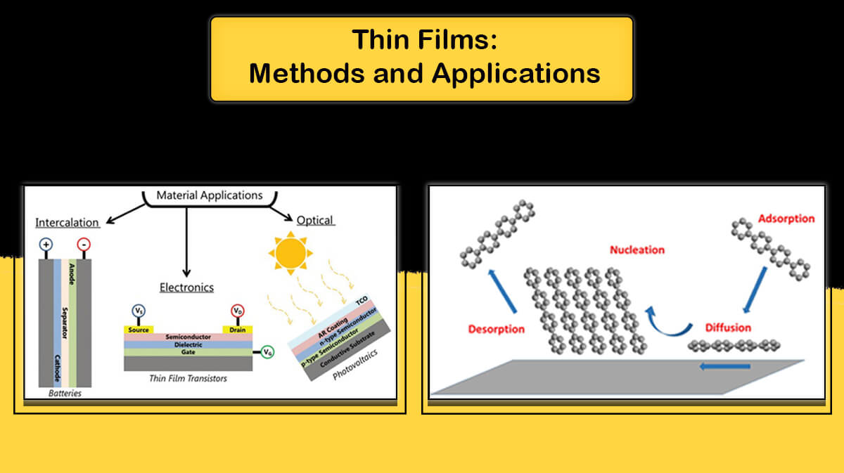
All of the high-vacuum Coating Systems manufactured by the Vac Coat Ltd., a designer and manufacturer of the vacuum systems, are equipped with turbomolecular pumps, including Desk Thermal Evaporator–DTT, High Vacuum Sputter Coater–DST1, Triple Target Sputter Coater–DST3, PLD, High Vacuum Carbon Coater DCT and etc. This makes these systems widely used in the microelectronics and Semiconductor industry, optics and lasers, Solar Cells, and etc.
For more information, refer to the following links please:
Some of Vac Coat Systems


References
- Ohring, Milton. Materials science of thin films: deposition and structure. Academic press, 2002.
- https://bit.ly/3yO9GDy
- John F. O’Hanlon (4 March 2005). A User’s Guide to Vacuum Technology. John Wiley & Sons. pp. 385 –. ISBN978 – 0 – 471- 46715-1.
- Marton, Kati (18 January 1980). Vacuum Physics and Technology . Academic Press. pp . 247 –. ISBN 978 – 0-08 – 085995 – 8.
- “Iqbal and Abdul Wasy et. al., NIMA – A, 2012 Design modification in rotor blade of turbo molecular pump”. Nuclear Instruments and Methods in Physics Research Section A: Accelerators, Spectrometers, Detectors and Associated Equipment. 678 : 88 – 90.
- https://bit.ly/3fPeZK8
- https://mmrc.caltech.edu/Vacuum/Pfeiffer Turbo/Turbos.pdf (Working with Turbopumps| Introduction to high and ultra high vacuum production, Pfeiffer Vacuum)