Sputtering Target Erosion
The sputter target surface undergoes erosion by successive collisions of the energetic charged particles through the magnetron sputtering process. The erosion pattern plays an important role in the sputter target lifetime or target utility; the more uniform the target erosion, the better the target utility. The target erosion patterns can be affected by several parameters, including the magnetic field over the target, geometrical properties of the target and the chamber, sputter process parameters, etc., which also influence the uniformity of the deposited layer by the coating process.
What is Target Erosion?
A sputtering target is sputtered by subsequent collisions of high-energy ions to the target surface, resulting in emerging erosion patterns on the target. These patterns are mainly affected by the shape of the plasma, magnetic field strength and shape in case of using magnetron cathodes, target shape, working pressure, and substrate-to-target distance.
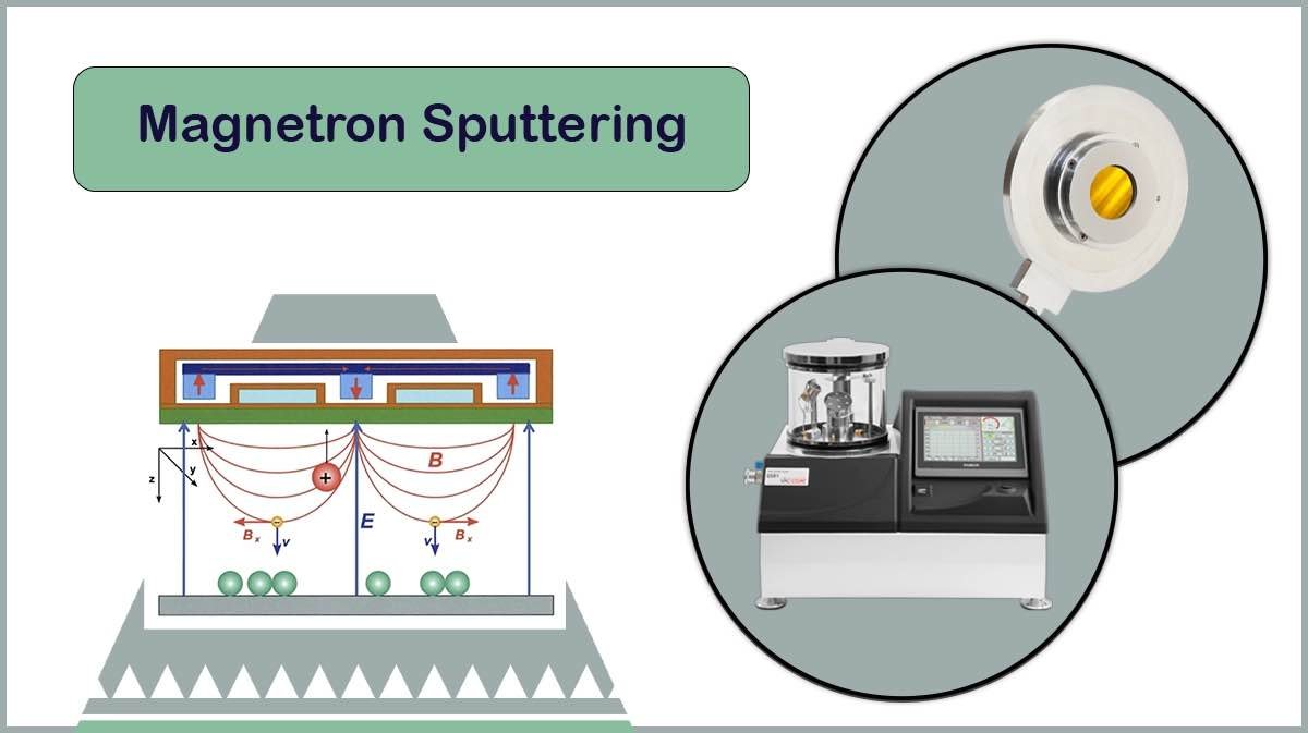
Charged particles created as a consequence of ion bombardment of target, tend to swirl above the target in the presence of magnetic field, undergo collisions with argon atoms and produce more free electrons and Ar+ ions. Charged particles confined to the target surface by the magnetic field collide with target, where erosion occurs (Figure 1).
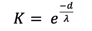
Collisions occur randomly when scattered particles move from the target to the substrate. The probability of this scattering is given by Equation (1):
 (1)
(1)
Here d is the distance, λ is the mean free path of a particle, and K is the probability of particle scattering. Applying an electromagnetic field changes the distribution of the electrons and a saddle-etched profile appears on the target surface, confirming that the sputtering rate is not constant at the target surface (Figure 1).
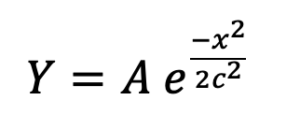
In general, finite element based simulations of magnetic field over the target are used to obtain the etching rate distribution of the etch ring. The Gaussian distribution of Equation (2) is used to simulate the depth of the etching ring.
 (2)
(2)
Where A is the etching depth, c is the etching width coefficient, Y is the etching depth distribution, and x is the coordinate of each point in the horizontal direction of the etching ring.

Angular Distribution of the Target Particle Sputtering
Based on Equation (3), the angular distribution of sputtering is investigated:
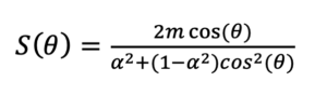 (3)
(3)
Where θ is the angle between the particle sputtering direction and the normal direction (Z direction) of the target surface, α = m/n ellipse coefficient, m ellipse length in the normal direction (Z direction) of the target surface, and n small axis of the ellipse in the tangential direction (X Direction).
Here, a cascade collision model based on momentum transfer theory can better explain the phenomenon of high-velocity particle bombardment that causes target particles to be sprayed. When the energy of radiative particles is high, almost all emissions are normal at the target level and virtually none are lateral. In contrast, the number of particles scattered near the target surface increases when the energy of the particles is low. As shown in Figure 2, the angular distribution curve is assumed to be an elliptical distribution.
Erosion Zone Features
In general, the shape of the erosion zone is a function of time, whereas the dynamic properties of particles, such as sputtering conditions, current density, diffusion and transport of dispersed particles during the coating process. When the target material is eroded, it shows a complex three-dimensional surface in macroscopic terms.
Target Shape Effect on the Erosion Pattern
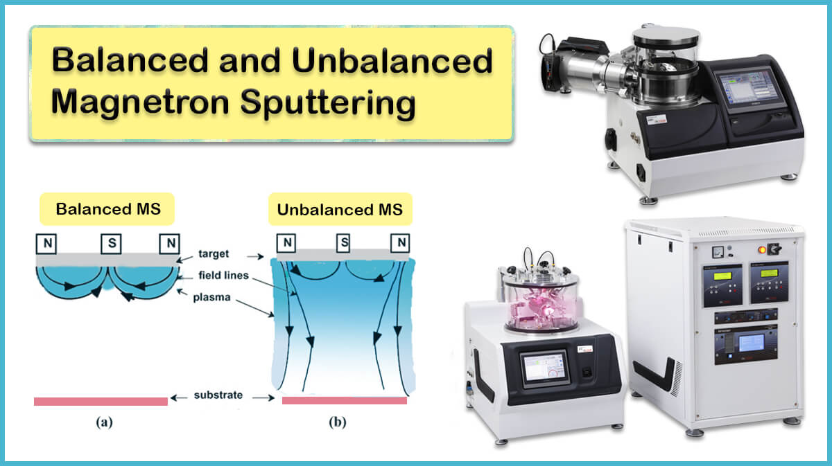
The erosion pattern of the target is related to the spatial distribution of the sputtered particles, which explicitly corresponds to the shape of the target and the cathode, as well as the type of magnetron, balanced or unbalanced. The balanced or unbalanced magnetron choices strongly shape the magnetic field over the target surface. The target shapes commonly used in research and industry are circular and rectangular, that are briefly reviewed here.

Circular Target
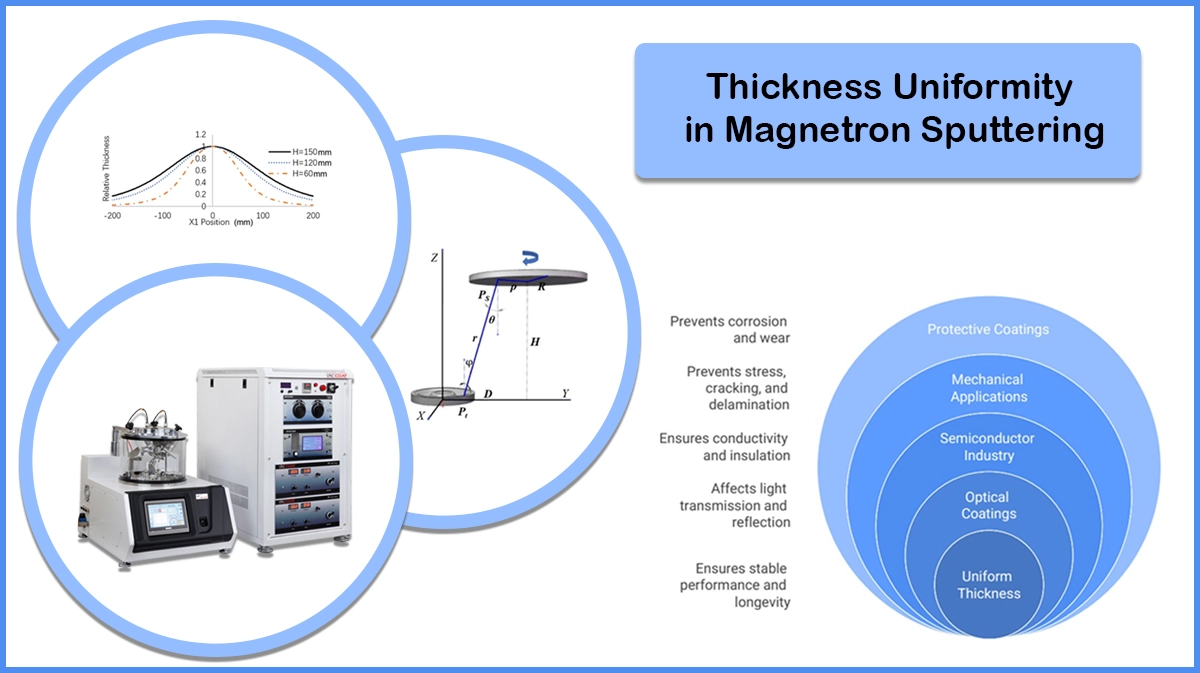
A circular (Round) target on a cylindrical magnetron cathode design is subjected to a homogeneous symmetric magnetic field over its surface. A simulation of the magnetic field lines over a cylindrical magnetron cathode is shown in Figure 3 below.
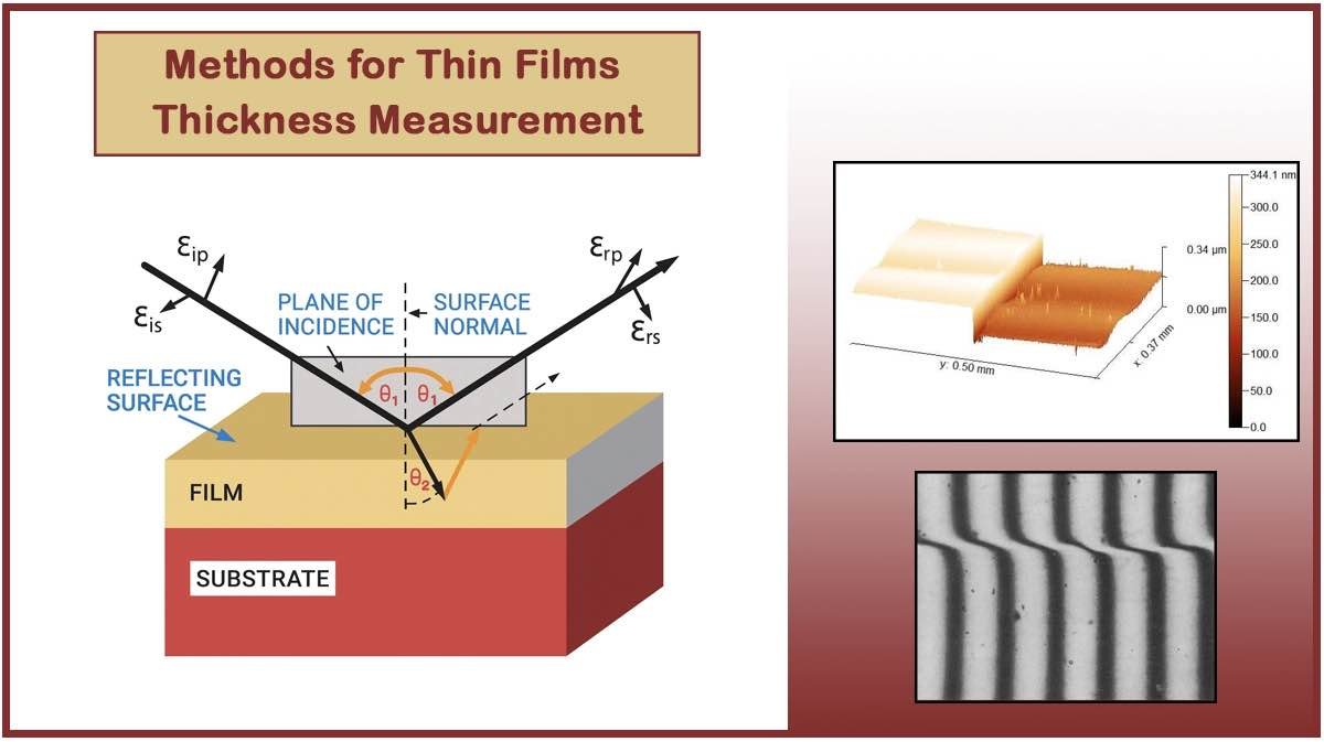
The round target erosion pattern and its effect on the uniformity of the deposited thin film are investigated in more detail in another article, “Thickness Uniformity of Thin Film Deposition by Magnetron Sputtering”.
Rectangular Target
For a rectangular copper target and argon process gas, the relation between thickness uniformity and target erosion area is depicted in Figure 5.
The calculations show that a proper reduction of the end-erosion zone (Δ) for a rectangular target also reduces the thickness uniformity. Conversely, a proper increase in the end-erosion area increases uniformity. Meanwhile, when Δ reaches a certain value, as shown in Figure 6 (b), the uniformity first increases and then decreases with increasing target-substrate distance.
The deposition rate is largely influenced by the size of the erosion zone, while the magnetron power, the target material and the pressure do not affect the distribution process. Thickness uniformity decreases with increasing distance of the target substrate and decreasing the erosion zone of the end of the target.
As the erosion zone of the end of the target increases slightly, the uniformity increases and then decreases as the target-substrate distance increases. There are two tendencies for thin film thickness uniformity with increasing length to width ratio of the target erosion area, i.e. it decreases slightly when the length is constant or increases when the width is constant. And the thickness of the thin layer decreases with decreasing power and increasing gas temperature. The deposition rate increases with decreasing target-substrate distance or increasing power and temperature.
Why Erosion Matters in Enhancing Sputter Target Utility?
A uniform erosion pattern across the target surface results in full target erosion during the sputtering process and reduces racetrack erosion on the target, which enhances target utility and lifetime.
How to Enhance Sputter Target Utility And Lifetime?
Enhancing sputter target utility, or in other words, sputter target lifetime, can be done by several techniques, including lowering process pressure, improving target heat transfer, target conditioning, and modifying the magnetic field over the target. Each way has a different impact, cost, and complexity level, which should be considered thoroughly beforehand.
Enhancing Target Thermal Conduction
Adding simple surface texturing, thinner backing, or improving the thermal interface between the target and the backing plate can enhance heat transfer between the target and the cathode. This helps to reduce hot spots, resulting in a more uniform erosion and higher control over sputter power.
Conditioning the Target
Cleaning the target surface outside the racetrack zone can maintain the conductivity of the complete target area, which can lead to more uniform collision of ions to the target surface.
Process Gas Pressure
The correct choice of the type of process gas and the chamber pressure can enhance the sputter yield and coating rate at the same plasma current, thus increasing the sputter target lifetime.
Argon gas is found to be more efficient in sputtering the target surface. So, fewer ion collisions to the target result in more sputtered target atoms.
Also, decreasing the working gas pressure during the sputter coating helps to enhance the charged particles’ mean free path to the target and the erosion pattern during the sputtering process, so increasing the utilised target area.
Magnetic Field Modification
The shape of the target erosion pattern is dependent on the strength of the magnetic field. For example, an increase in the magnetic field strength will make the race track narrower, using a confined area of the target surface.
This erosion pattern limits the use of sputter targets to only a fraction of the initial mass. The magnetic field modifications can be performed through several techniques, including:
- Improving the Magnetron Design: Magnetron design plays a pivotal role in target utilisation. Optimising the magnetic field by techniques such as reshaping or repositioning the magnets, or omitting the central part of the target, can significantly enhance the magnetron efficiency, improving the target utilisation from 20–30% to 50–80%.
- Scanning Magnetic Field: A moving magnetic field beneath the target surface enlarges the area exposed to the energetic ions in the plasma, which causes a more uniform target erosion pattern across its surface.
- Using a Ferromagnetic Shunt: Ferromagnetic pieces near the magnet ring or pole shims can locally reshape magnetic field lines, which alter the target erosion pattern. The correct choice of the ferromagnetic pieces’ shape, type, and position can temporarily modify the magnetic field lines and make them smoother on the target surface, resulting in a more uniform erosion pattern and enhanced sputter target lifetime.
Conclusion
The sputter target utility, or target lifetime, highly depends on the erosion pattern caused by the collision of energetic charged plasma particles onto the target surface. The erosion patterns of the circular and rectangular sputter targets are studied in detail in this article. Also, the innovative solutions to improve the target erosion pattern to enhance sputter target utility, such as modifying the magnetic field of the magnetron cathode, are reviewed here.
Some of Vac Coat's Products


References
- Schoff, M. E. (2009). Sputter target erosion and its effects on long duration DC magnetron sputter coating. University of California, San Diego.
- Nouvellon, Corinne, et al. “Target utilization improvement by pole pieces insertion in a magnetron sputtering target.” Plasma Processes and Polymers 4.S1 (2007): S637-S639.
SHON, C. H., KIM, U. S., Deok-Woo, H. A. N., & SUNG, Y. M. (2009). Enhancement of the Usage of Cathode Materials in a Magnetron Sputter. J. Plasma Fusion Res. Series, 8.
- https://ravescientific.com/resources/education/34-optimizing-the-usage-of-sem-sputter-targets#:~:text=Reduce%20the%20coating%20thickness%20%E2%80%93%20resistivity,efficiency%20of%2025%2D30%25.
- https://matsight.com/case-studies/improving-sputtering-cathodes-and-targets-using-simulation/
- https://www.acetron.net/corporate-news/what-is-the-lifetime-of-a-sputtering-target.html
- https://www.gencoa.com
- https://www.dextermag.com/enhancing-sputtering-magnetron-design/#:~:text=Lower%20operating%20pressures%20translate%20to,erosion%20across%20the%20target%20surface.
- https://angstromsciences.com/profiled-magnet-array
- Moh, C. B., Chin, C. C., Teh, K. S., & Lai, J. Y. (2014). U.S. Patent No. 8,685,214. Washington, DC: U.S. Patent and Trademark Office.