
Effect of Chamber Ultimate Pressure on Carbon Coating
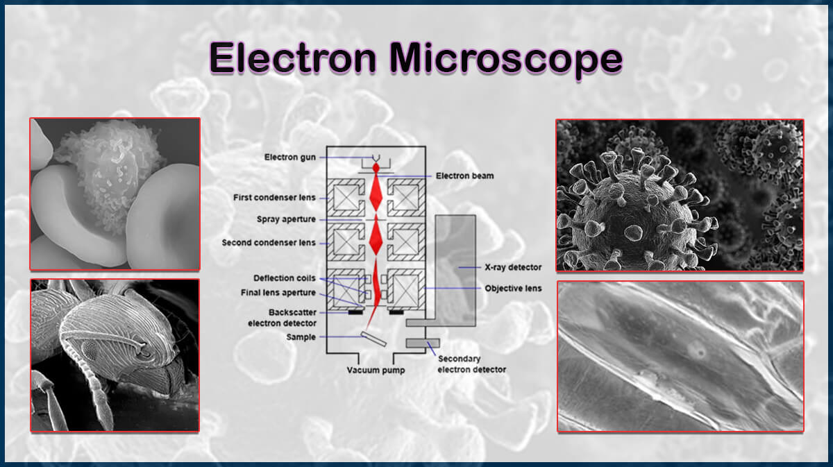
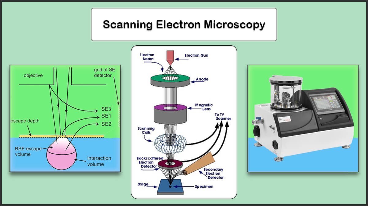
Electron microscopy is a method to image samples, which provides much higher resolution and further details compared to traditional optical microscopes. Samples should be conductive for this analysis, so a conductive layer is normally deposited on the sample surface to image nonconductive surfaces. Carbon is one of the common materials used for sample preparation for electron microscopy, but carbon coating needs a vacuum chamber to reach required conductivity [1].
Carbon can be coated in a low-vacuum or high vacuum system, choosing each results in different coating structure. In a typical low-vacuum system (ultimate pressure of about 10-3 mbar), carbon atoms have shorter mean free path, hence suffer multiple collisions, and scatter widely. Also, surface diffusion of carbon atoms makes this method more suitable for coating rough samples, and depositing tough carbon thin films. These coatings are mainly useful for preparing samples for X-ray analysis and cathodoluminescence [2].
Otherwise, in a high vacuum system (typical 10-5 mbar range or better), the lower background pressure indicates lower amounts of reacting molecules on the way of carbon atoms, like nitrogen, oxygen, and water vapor, which leads to deposition of dense amorphous carbon thin films with high purity [3]. Consequently, carbon films structure is not resolvable by SEM (Scanning Electron Microscopy) or FESEM (Field Emission SEM) imaging; hence, these coating systems are advantageous for FESEM, TEM (Tunneling Electron Microscopy), microprobe and EBSD (Electron Backscatter Diffraction) sample preparation.
Whereas, lower vacuum systems with rotary pumping deposit structured carbon layer which can be revealed at about 25,000x magnification, suitable for standard SEM/EDS applications [4]. Moreover, carbon thin film deposited in a low-vacuum coating chamber may not produce enough secondary electrons [2], which is unfavorable in electron microscopy imaging (Figure 1).
![Figure1. Surface morphology and cross-sectional images of carbon coated in 3.3 kPa (up) and 8.6 kPa (down)[5] Surface Morphology and Cross-Sectional images of Carbon Coated](https://vaccoat.com/wp-content/uploads/Figure1.-Surface-morphology-and-cross-sectional-images-of-carbon-coated-in-3.3-kPa-up-and-8.6-kPa-down5.jpg)
In carbon evaporating method, common carbon sources are pre-shaped carbon rods or woven fiber carbon (Figure 2). These two forms of carbon sources can result in distinct layer deposition conditions, which are listed below in Table 1.
![Figure2. Typical carbon fiber (right) and carbon rod (left) used in carbon coatings [4]. Typical Carbon Fiber and Carbon Rod Used in Carbon Coatings](https://vaccoat.com/wp-content/uploads/Figure2.-Typical-carbon-fiber-right-and-carbon-rod-left-used-in-carbon-coatings-4..png)
Table1. Carbon coating parameters due to different carbon source shapes
| Carbon Rod | Carbon Fiber | |
| Purity | High, because of its low surface area | Contains adsorbed contaminants due to its high surface area |
| Carbon Layer Thickness | Easily controlled between 1-50 nm from a single rod | Carbon fiber diameter controls thickness |
| Thickness Control | Controlled by power and evaporation time | No control in flash evaporation, controllable in pulsed mode |
| Power | Powerful source needed (100-200A) | Less power needed (approx. 50A), low risk of thermal damage to frozen sample |
| Multiple Evaporation Possibility | Multiple evaporation with one set of rods | Normally source needs reloading after each evaporation |
Vac Coat Carbon Coaters
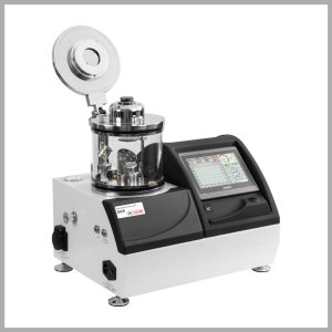
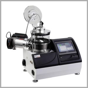
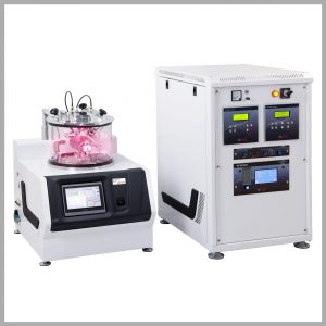
Vac coat Ltd. produces sputter and carbon coating systems with interchangeable carbon rod/fiber evaporation head, with high current power supply for carbon rod and improved carbon fiber coating features in DSCR, DSCR-300, DSCT, and DSCT-T models (Figure 3). The small chamber of sputter and carbon coater is able to perform pulsed carbon fiber evaporation. Short pulses provide more controlled deposition and significantly reduces the amount of debris associated with traditional carbon deposition.
Besides, the ability of loading several carbon fibers allows coating thicker carbon film if it’s required. The DCT, DSCT-T, and DSCT models use turbomolecular pumps to provide high vacuum carbon coating for SEM, FESEM, EDS/WDS, TEM, and EBSD sample preparation; where DCR and DSCR models are rotary pumped carbon coaters in low vacuum mainly used for SEM/EDS standard sample preparation. The DCT and DCR models are carbon coaters provided with carbon fiber evaporation head.
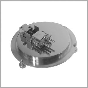
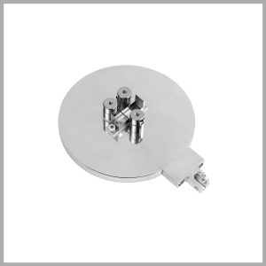
Figure3. Carbon Rod (Left) and Carbon Fiber (Right) Heads for DSCT-T Model
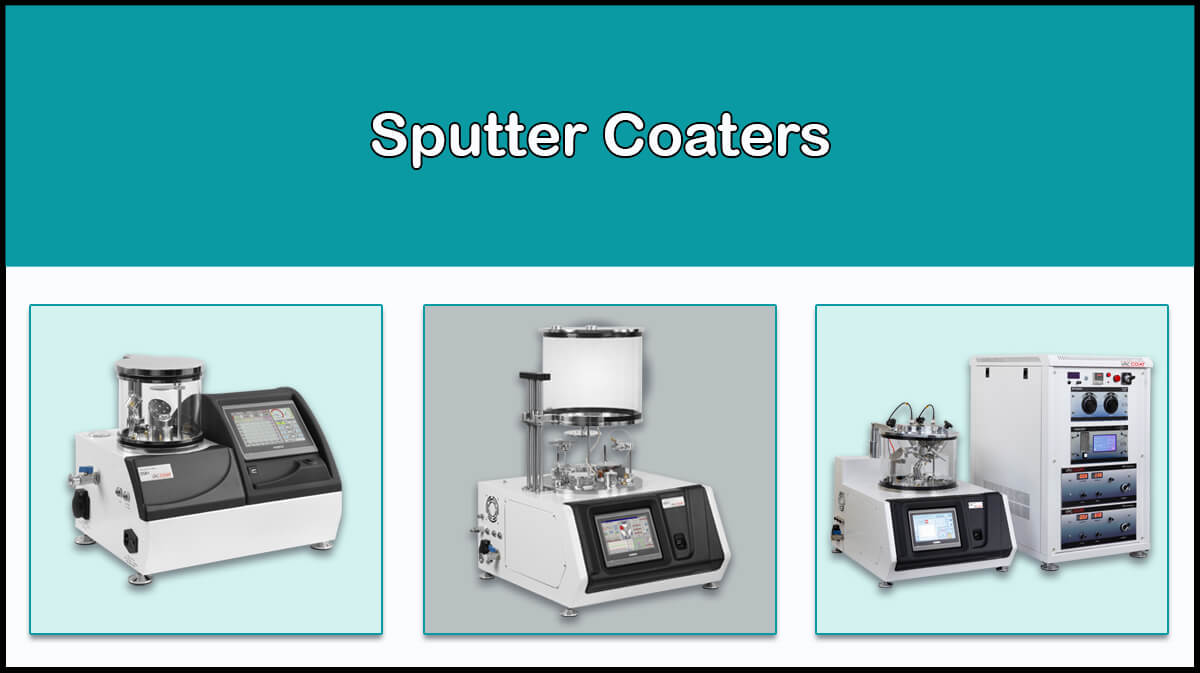
Vaccoat also produces other vacuum deposition systems such as desk sputter coater (DSR-1) with rotary pump and turbo pumped triple target sputter coater (DST3-T) equipped with RF (RF Sputtering) and DC power supplies, which can switch between thermal evaporation and sputtering condition for thin film deposition. For more information, please visit the website.
References
- Heu, R., Shahbazmohamadi, S., Yorston, J., & Capeder, P. (2019). Target Material Selection for Sputter Coating of SEM Samples. Microscopy Today, 27(4), 32-36. doi:10.1017/S1551929519000610
- Goldstein, J.I. et al. (1992). Coating and Conductivity Techniques for SEM and Microanalysis. In: Scanning Electron Microscopy and X-Ray Microanalysis. Springer, Boston, MA. https://doi.org/10.1007/978-1-4613-0491-3_13
- https://www.quorumtech.com/tag/carbon-coating/
- https://www.tedpella.com/carbon_html/carbon-evaporation-rods-versus-fibers.aspx
- Mubarak Ali, Mustafa Urgen, “Morphology and Structure of Carbon Films Deposited at Varying Chamber Pressure”, arXiv:1802.00730v20 [cond-mat.mtrl-sci]









What is the proper coating condition for preparing carbon replicas for TEM imaging?
Carbon replicas are required to have an amorphous structure to prevent any interference in the imaging for TEM, which can be achieved by thermal evaporation of carbon under high-vacuum condition. Thus we strongly recommend our DCT model for preparing carbon replicas for TEM imaging.