High Vacuum and Ultra-High Vacuum Systems
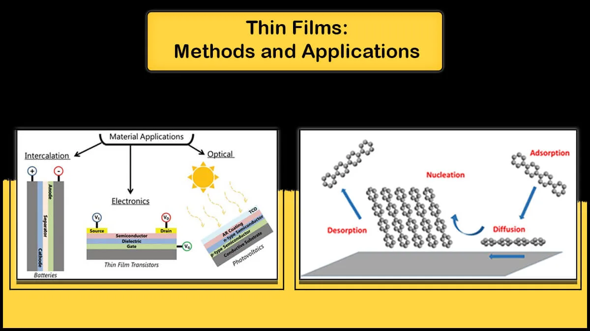
High vacuum and ultra-high vacuum conditions are used in applications where a highly clean environment is required. In the absence of unwanted particles, clean processes like thin film deposition and precise surface analysis techniques are made possible.
What is High Vacuum Pressure?
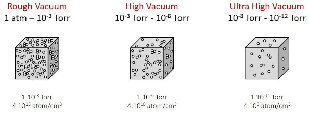
Vacuum means no material, so what is measured as the vacuum pressure is the residual gas pressure in the chamber. Three different units of expression are usually used to express the pressure: Pascal (Pa), Torr, and bar. Vacuum quality is also usually classified into three categories: Rough vacuum, High vacuum (HV), and Ultra-high vacuum (UHV). High vacuum pressure is called the pressure in the of 10-3 to 10-8 Torr, and lower pressures are in the ultra-high vacuum region.
Where Do We Need Vacuum?
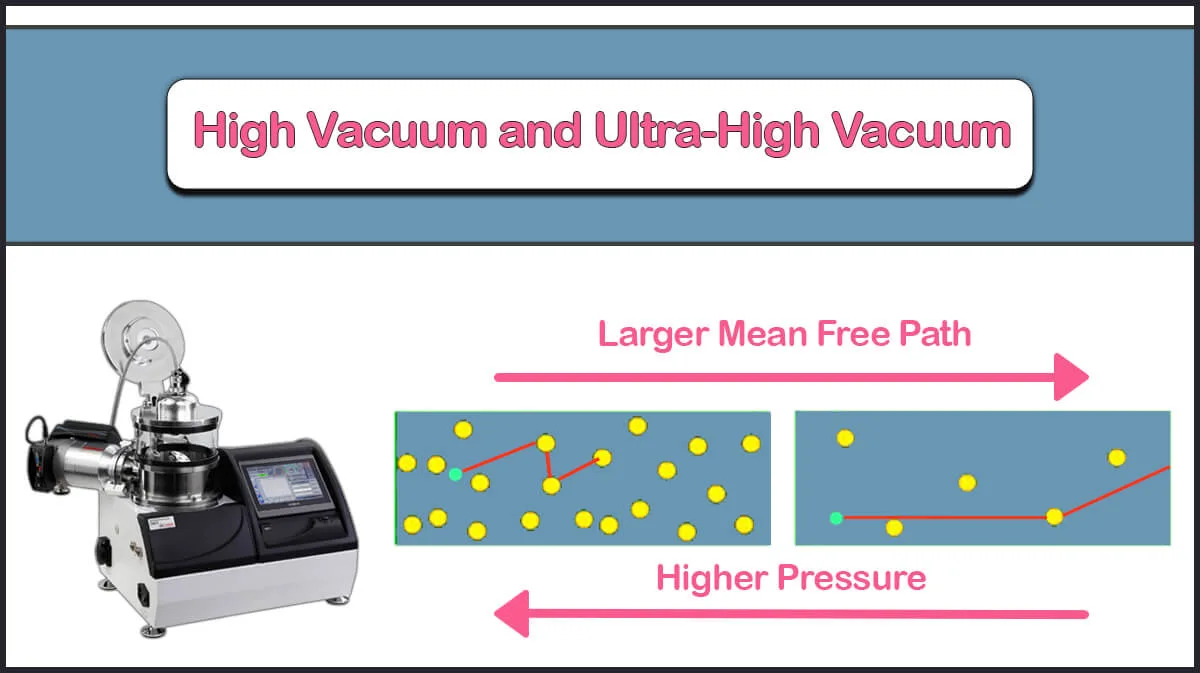
When an ionic or electron beam collides with particles (Residual gas inside the chamber), it may deviate from its path, divide, or even react with that particle. As a result, the presence of unwanted particles in the system will reduce its efficiency. Mean Free Path (MFP) is the average distance traveled by a gas molecule before colliding with another gas molecule. In extremely high vacuum conditions, the average free path of gas molecules is approximately 40 km. So the gas molecules have very little contact with each other and will collide with the chamber walls and surfaces in the vacuum chamber many times before they collide with each other.
High Vacuum or Ultra-High Vacuum Pressure, Which One is Better?
Depending on the application, the main issue is not the amount of chamber pressure but the contamination of the sample in the vacuum chamber. The more gas molecules residues present in the chamber, the more the sample surface will absorb the atmospheric particles. Relying on the duration and needed purity for the procedure, one can decide whether HV or UHV is needed.
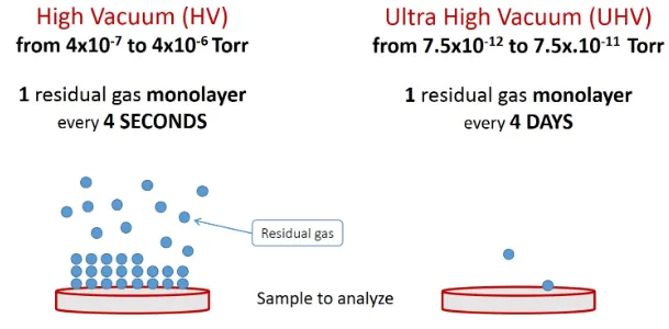
UHV systems require more expensive facilities and caring, but where high accuracy and purity are vital, the vacuum should be as high as possible. An ultra-high vacuum chamber provides suitable conditions for more accurate surface analysis processes. Indeed, surface contamination with an unwanted monolayer takes only 4 seconds in the HV range, while in the UHV range, it lasts about 4 days.
How to Reach Lower Pressure Levels?
Reaching higher levels of vacuum requires the use of special materials and various stages of pumping. Seals and gaskets used in the UHV system should prevent even minor leaks. Almost all of these seals are made of metallic materials with knife edges on both sides cutting into a soft gasket, typically copper. These all-metal seals can maintain integrity to UHV ranges.
Vacuum Chamber Materials
The materials used in UHV conditions should not present high vapor pressure and need to stand heating at more than 120°C for many hours/days, called baking out. So, it is not possible to use plastics, PTFE, PEEK neither glue (Screws are used instead), or lead (Soldering). This is why UHV systems are more expensive than HV ones. The baking process causes the gas atoms to leave the inner surface of the chamber wall. During the vacuuming process, the gas atoms absorbed onto the chamber wall are slowly released (Outgassing Phenomenon), if the chamber is not baked, it will take months to reach UHV conditions. Minimizing the internal chamber surface can also help to reduce the amount of outgassing.

Clean Environment
Preparing a clean environment is mandatory to reach high vacuum and ultra-high vacuum levels. Using clean gloves and using clean surfaces as samples or individual components inside the chamber will help to vacuum the system to lower pressures, while UHV systems are generally required to be placed in a clean room to maintain ultra-high vacuum conditions.
HV and UHV Vacuum Pumps
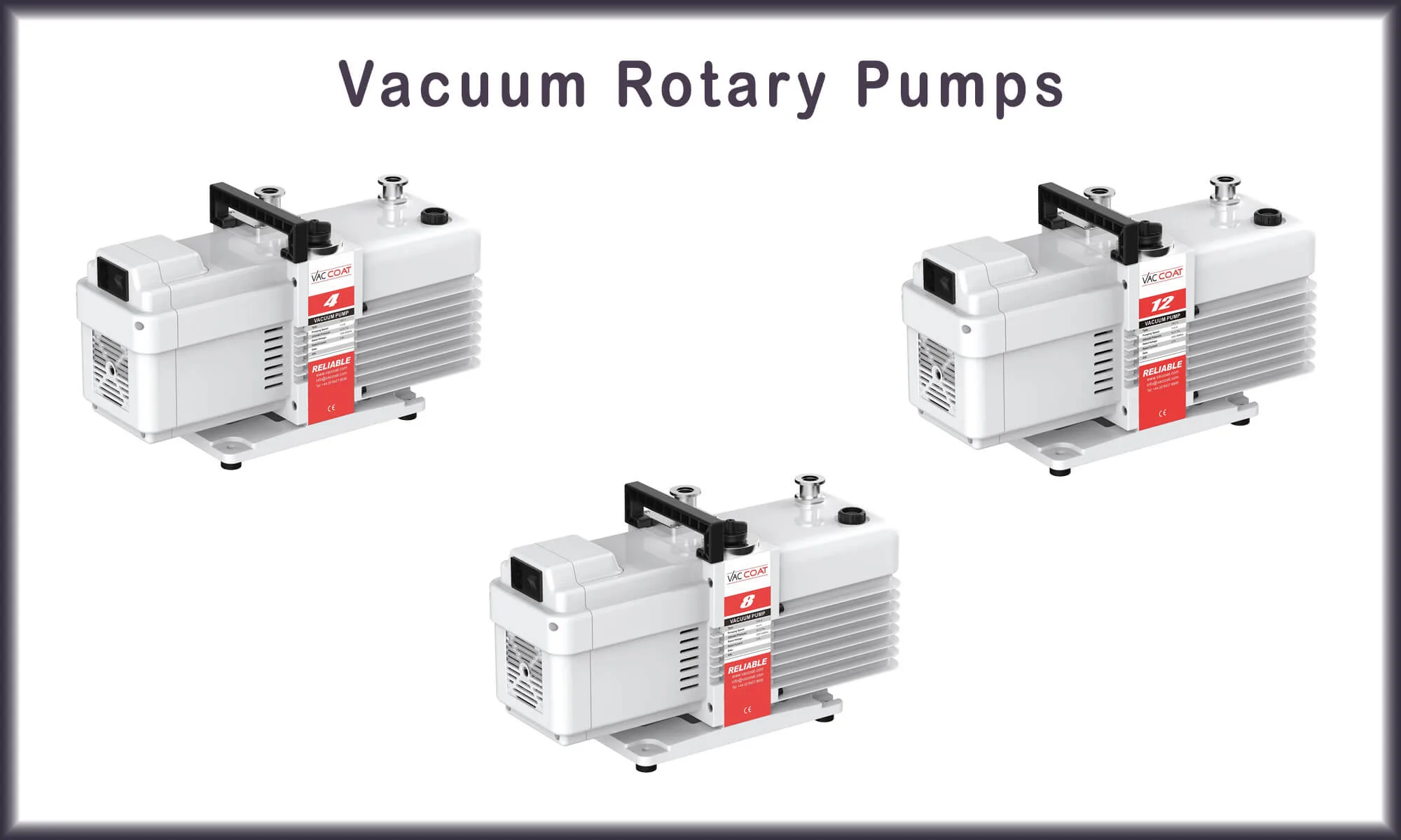
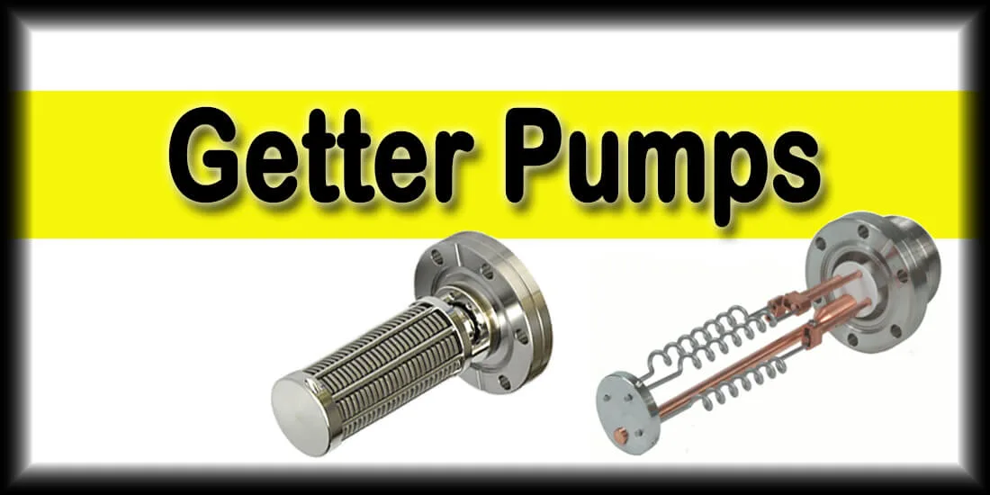
Two or more pumps must be used to reach the HV and UHV conditions. No pump can reduce pressure from the atmosphere to high vacuum levels alone. In the first step, a rough pump, called a backing or fore pump, reduces the pressure to a low vacuum of nearly 1 mTorr (Rough Vacuum). Then by a secondary vacuum pump commonly used in the second stage, including turbomolecular pumps, ion pumps, diffusion pumps, ion getter pumps, and cryogenic pumps the pressure reaches lower amounts.

The Pump Conductance
The conductance of a pump is considered the inverse of the pump flow resistance. The pump conductance is defined as the flow of gas through a piping or between two openings divided by the pressure drop between the two sides with the dimension of volume per unit time. It determines how easily a vacuum system can allow the flow of gas through it.
The Barriers on the Way of Achieving High Vacuum
Leakages
The leakage of the system is one of the problems that any vacuum system will face sooner or later, which causes the system not to achieve the desired pressure.
Leaks can be divided into Real and Virtual ones. Real leaks occur due to the openings that arise in a vacuum chamber and its connections. If the vacuum pump is turned off, the pressure will gradually increase and eventually reach atmospheric pressure in the presence of huge leaks, while virtual leaks appear at higher vacuum levels and are typically due to trapped air or water in something like a tiny hole inside the vacuum chamber, whose gradual release will not allow the vacuum pump to reduce the pressure. Therefore, it is needed to find out if it is a real leak or a virtual one to detect the leak.
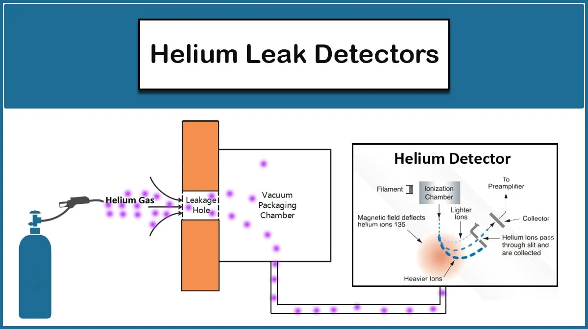
In case of real leaks, leak detection can be performed by utilizing a Helium leak detector, which is an expensive method. But there are more affordable ways, depending on the leak origin, that are mentioned in the Leak Detection article on the Vac Coat blog.
Outgassing
Outgassing is one of the problems that needs to be addressed to reach HV and UHV conditions. All materials, even materials that are not usually absorbent, also exhibit the outgassing phenomenon, such as some metals and plastics. For example, vessels lined with a highly gas-permeable material such as palladium (which highly absorbs hydrogen species) create special outgassing problems.
Outgassing can occur from two sources: surfaces and bulk materials. Outgassing from bulk materials is minimized by the selection of materials with low vapor pressures (such as glass, stainless steel, and ceramics) for everything inside the system.
At very low pressures, the gases absorbed by the surfaces in the vacuum chamber are gradually released, preventing the pressure from reaching the UHV range. Water is one of the things that strongly causes outgassing. By venting the vacuum chamber with air, a thin layer of water vapor is absorbed on the surfaces and released to the vacuum chamber during low-pressure processes. Removal of water and similar gases generally requires baking the UHV system while vacuum pumps are running. When running UHV processes the chamber can be chilled using liquid nitrogen to reduce further outgassing.
UHV systems are usually 100 percent dry and there should be no water or moisture in them. The most common gas remaining in UHV systems is hydrogen. Hydrogen is a light, mobile gas that is hard to pump out. Pumping out this gas requires special UHV pumps and reducing the amount of hydrogen released from the inner surface of the vacuum chamber is one of the things that should be taken into consideration.
How to Measure the Vacuum Pressure?
For measuring the pressure in the HV and UHV ranges, the use of conventional gauges is not suitabledue to the outgassing phenomenon, so ionization gauges are used instead. These gauges use the probability of gas ionization to determine the particle number density. Two types of ionization gauges are discussed below:
Cold Cathode Pressure Gauge
A cold cathode ionization gauge is often referred to as a Penning Gauge. The action mechanism of these pressure gauges is that the electrons generated by applying a strong electric field between the cathode and anode are accelerated and collide with the gas atoms in the chamber in their path. As a result of these collisions, the gas atoms become ionized and the released electrons reach the collector and an electric current passes through the circuit.
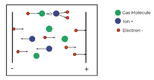
Figure 3. Cold cathode pressure gauge
As the gas pressure increases inside the chamber, the number of charge carriers also increases, and so does the electric current. By measuring the electric current, the pressure inside the chamber is determined. These gauges can measure the pressure in the range of 10-2 to 10-5 mbars.
Hot Cathode Pressure Gauge
In a hot cathode pressure gauge, the cathode acts as an electron-emitting source. The electrons are sent from the cathode to the anode, collide with the gas atoms in their path, and ionize them. The measurement of the number of ions in the ion collector results in the determination of the pressure inside the chamber. These gauges can measure the pressure in the range of 10-2 to 10-11 mbars.
If the particle density inside the vacuum chamber is high, the ions cannot reach the ion collector. This is why cold cathode gauges are used at high pressures and in the early stages of vacuuming, and hot cathode gauges are used at lower pressures. The electrons emitted from the cathode can produce X-rays colliding with the anode surface. The resulting X-rays also emit electrons from the ion collector, resulting in an offset current. So, shields are commonly used to protect the ion collector from X-rays in recent years.
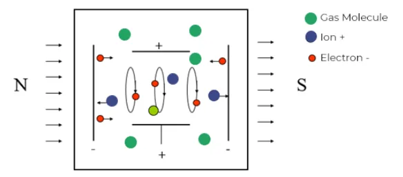
Figure 4. Hot cathode pressure gauge
High Vacuum and Ultra-High Vacuum Applications
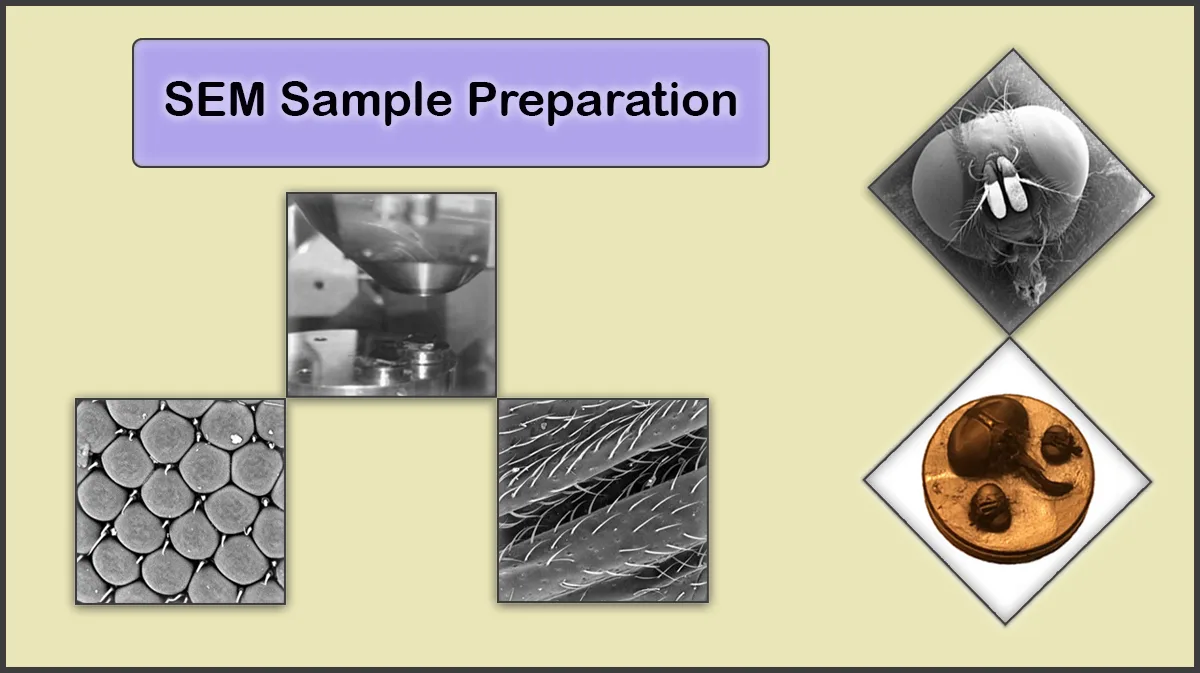
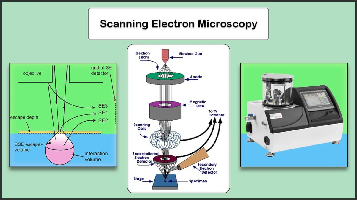
Surface Analysis
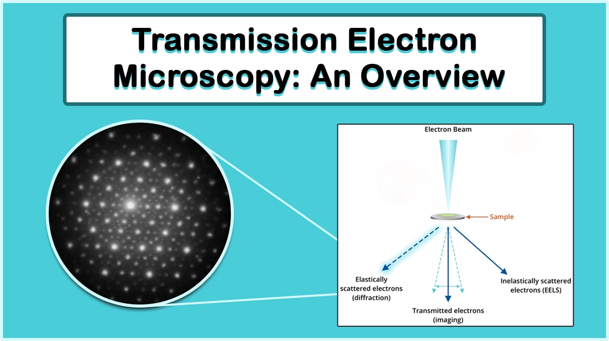
Sample preparation for scanning electron microscopy (SEM) by sputtering of noble metals or thermal evaporation of carbon sources can be performed in rough vacuum levels, however, high vacuum conditions are essential for the deposition of oxidizing metals and achieving finer grain size coatings, desirable for FESEM, TEM, and high-resolution imaging.
Ultra-high vacuum conditions are required in many surface characterization techniques to reduce surface contaminations and let low-energy particles aroused from the sample surface reach the detectors without suffering collisions. This feature enables surface analysis techniques such as X-ray photoelectron spectroscopy (XPS), Auger electron spectroscopy (AES), secondary ion mass spectrometry (SIMS), thermal desorption spectroscopy (TPD), Angle-resolved photoemission spectroscopy (ARPES), Atom Probe Tomography (APT), or field emission microscopy (FEM).
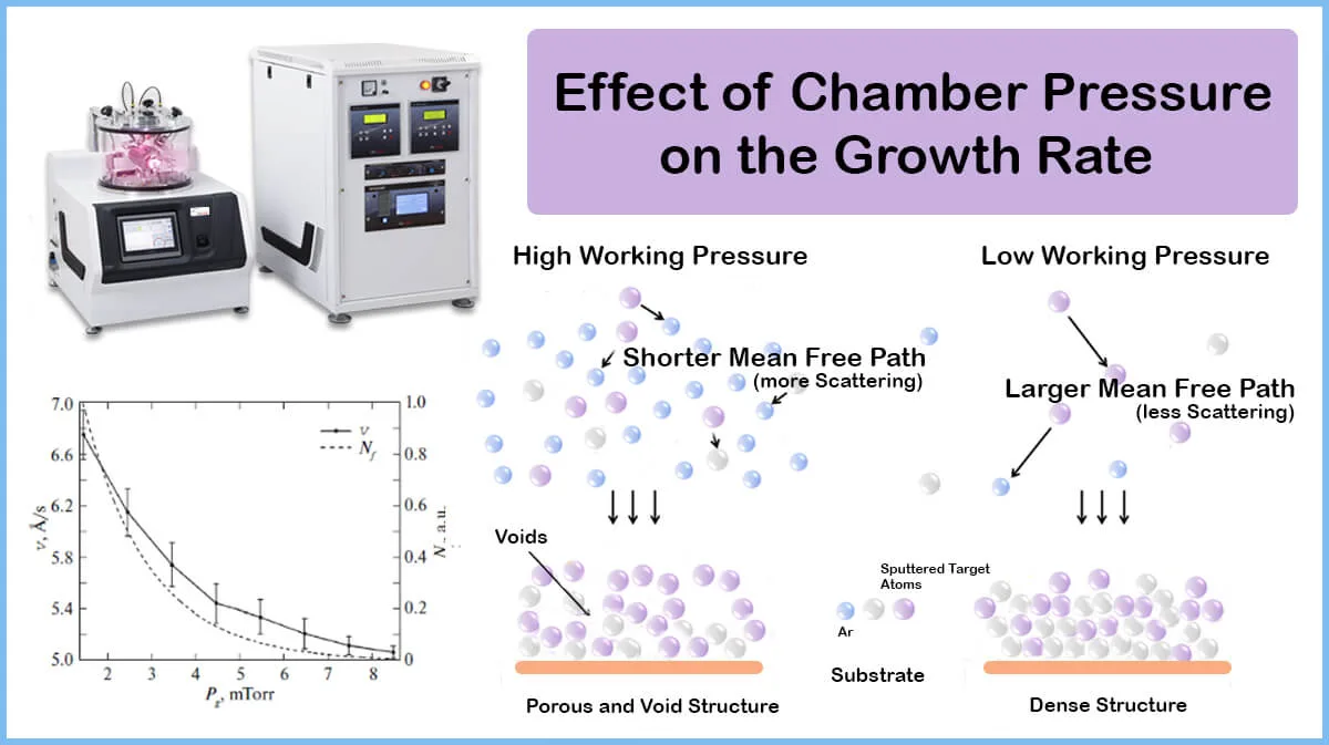
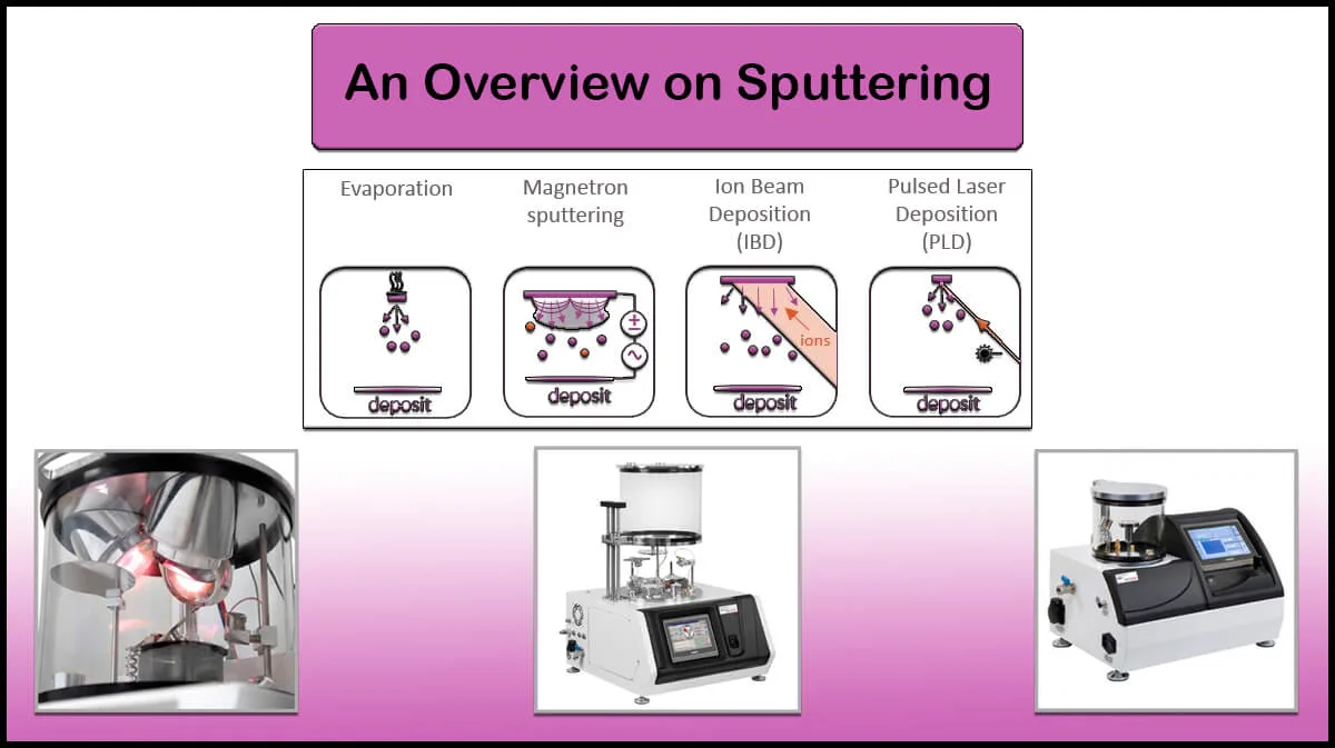
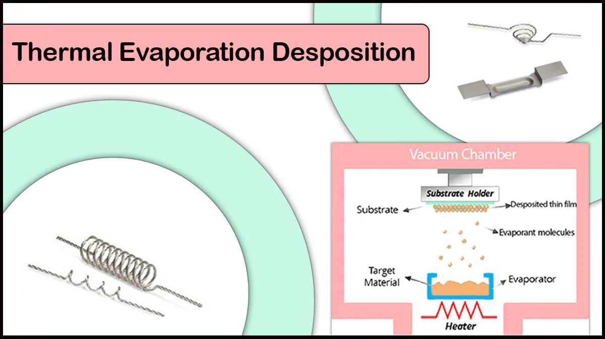
Thin Film Deposition
High vacuum chambers are useful in thin film deposition by PVD techniques like sputtering and thermal evaporation deposition.
UHV chambers can be useful in the growth of pure thin film and preparation techniques like molecular beam epitaxy (MBE) and atomic layer deposition (ALD).
Research Applications
Some High-tech research applications like particle accelerators or gravitational wave detectors require UHV conditions to reduce undesired collisions and perturbations from the outer environment.
Vac Coat High Vacuum Deposition Systems
Vac Coat thin film coating systems work under vacuum conditions to perform physical vapor deposition techniques. Vac Coat high vacuum sputter coaters, carbon coaters, and thermal evaporators are equipped with a turbomolecular pump to provide a clean chamber environment to achieve a low-contamination thin film deposition. DST1 and DST3 single and triple cathode high vacuum sputter coaters, DCT carbon coater, DSCT-T triple head sputter and carbon coater with thermal evaporator, and DTE and DTT thermal evaporators are among the popular Vac Coat high vacuum coaters useful in electronics, optics, and photonic industry.
For more information on ultra-high vacuum systems, see the below links.

Vac Coat offers high-vacuum DTE and DTT desk thermal evaporators optimized for the deposition of different materials’ thin films by thermal evaporation methods.
Vac Coat company offers different carbon coaters and hybrid sputter & carbon coaters suitable for electron microscopy sample preparation and research purposes.
Vac Coat Ltd. produces and designs different types of sputter coaters systems. Sputtering is a method to deposit thin films of various materials on a substrate.


Some of Vac Coat Products


References
- https://www.vacuumscienceworld.com/ultra-and-extreme-high-vacuum#leak_detection_in_high_ultra__extreme_high_vacuum
- http://www.orsayphysics.com/what-is-uhv
- Strong, John (1938). Procedures in Experimental Physics. Bradley, IL: Lindsay Publications., Chapter
- B. Schläppi, et al. (2010), Influence of spacecraft outgassing on the exploration of tenuous atmospheres with in situ mass spectrometry, J. Geophys. Res., 115, A12313, doi:10.1029/2010JA015734.
- https://www.edwardsvacuum.com/en-uk/knowledge/applications/working-under-hv-uhv-conditions
- https://en.wikipedia.org/wiki/Ultra-high_vacuum